Printing apparatus capable of effectively heating and cooling ink

a printing apparatus and inkjet technology, applied in printing, other printing apparatus, etc., can solve the problems of increasing the amount of ink in the circulation route, degrading the heating efficiency of the heater, and so as to reduce the amount of circulating ink and increase the rate of raising the ink temperature. , the effect of shortening the path length

Active Publication Date: 2009-10-15
RISO KAGAKU CORP
View PDF4 Cites 10 Cited by
  • Summary
  • Abstract
  • Description
  • Claims
  • Application Information

AI Technical Summary

Benefits of technology

[0016]The first reference temperature may be the lower limit of a warranty temperature range of ink defined to ensure print quality, and the second reference temperature may be the upper limit of the warranty temperature range. Also, in a preferred embodiment, the heater side route may have a shorter path length than the cooler side route. By this configuration, it is possible to reduce the amount of the circulating ink when the ink temperature is low, and therefore to further increase the rate of raising the ink temperature by the heater. Furthermore, in a preferred embodiment, the switch mechanism switches the ink circulation route only when the print process is not in progress for the purpose of preventing ink pressure variation due to switching of the switch mechanism from affecting the print process.

Problems solved by technology

Because of this, the heating efficiency of the heater is often degraded by the provision of both the heater and the cooler.
For example, while the cooler is provided with a heat sink and a fan, heat dissipation occurs from ink at the heat sink during heating the ink by the heater when the ink temperature is too low, so that the heating efficiency is degraded.
Also, since the ink has to be passed through the heater and the cooler, the circulation route of the ink becomes long, so that the amount of ink increases in the circulation route.
Because of this, it takes much time to heat the ink to an appropriate temperature by the heater.

Method used


Image

  • Printing apparatus capable of effectively heating and cooling ink
  • Printing apparatus capable of effectively heating and cooling ink
  • Printing apparatus capable of effectively heating and cooling ink

Examples


first example

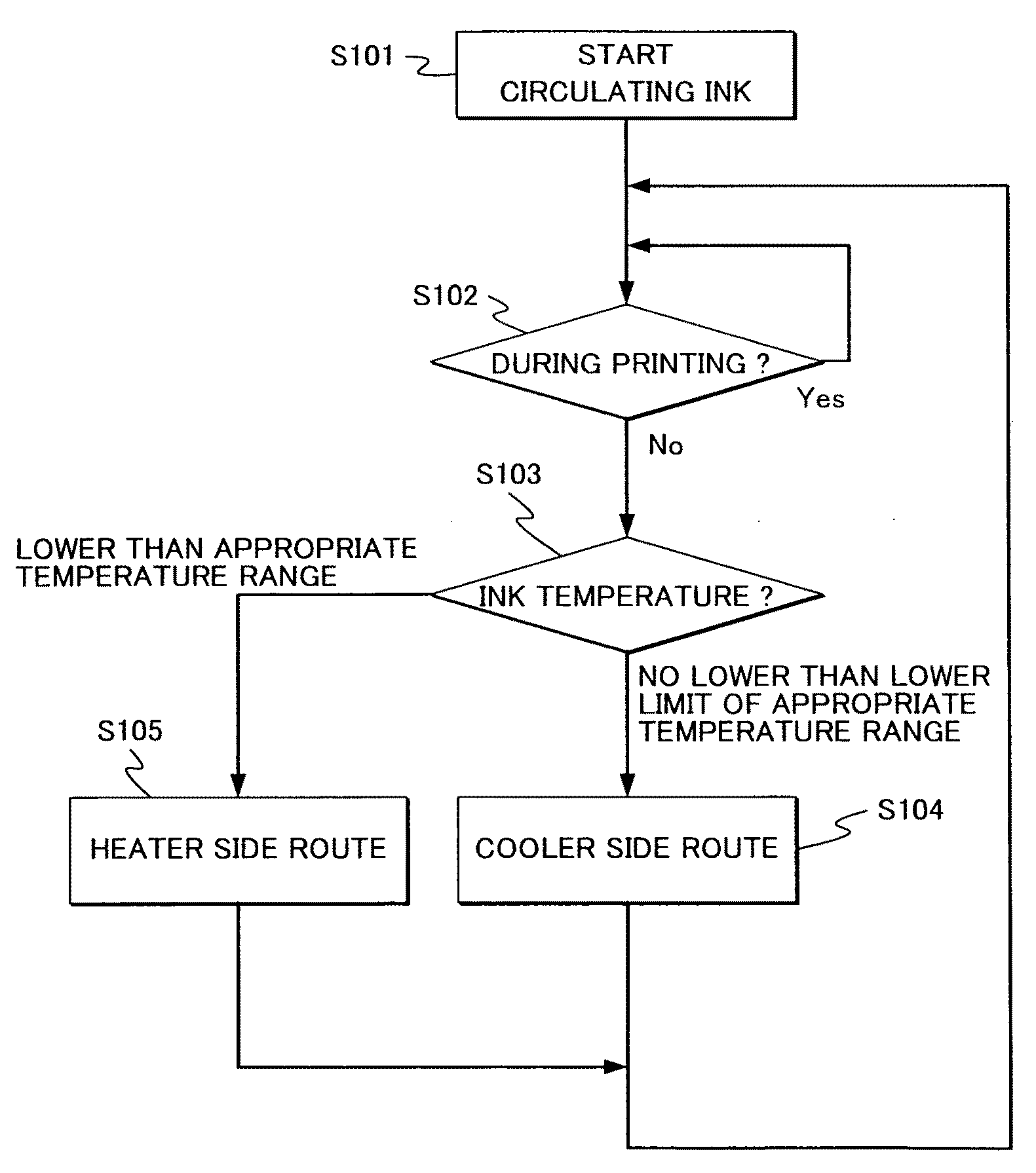
[0046]Next is a description of a first example of controlling the ink temperature in the ink jet printer 10 having the aforementioned configuration. FIG. 3 is a flow chart for showing the process of switching the solenoid valve 170 by the ink temperature control unit 220 of the control unit 200 in accordance with this first example. A lower limit and an upper limit are determined in advance to define an appropriate temperature range or a warranty temperature range of ink. The control unit 200 performs the process of switching the solenoid valve 170 with reference to the ink temperature as measured by the ink thermometers 120b on the basis of the appropriate temperature range.

[0047]First, in advance of starting the print process, the pump 140 is driven to start circulation of ink in step S101. Switching the solenoid valve 170 is performed only when the print process is not in progress for the purpose of preventing ink pressure variation due to switching of the solenoid valve 170 from...

second example

[0063]Next is a description of a second example of controlling the ink temperature in the ink jet printer 10 having the aforementioned configuration. FIG. 5 is a flow chart for showing the process of switching the solenoid valve 170 by the ink temperature control unit 220 of the control unit 200 in accordance with this second example. In the case of the present example, the ambient temperature of the ink jet printer 10 is referred to and further taken into consideration for switching the solenoid valve 170. Namely, the ambient thermometer 180 provided for the ink jet printer 10 measures the ambient temperature inside or outside the ink jet printer 10. In the case of the second example, the ambient temperature is further taken into consideration because the temperature of the ink is influenced by the ambient temperature.

[0064]First, in advance of starting the print process, the pump 140 is driven to start the circulation of ink in step S301. Switching the solenoid valve 170 is perfor...

third example

[0069]Next is a description of a third example of controlling the ink temperature in the ink jet printer 10 having the aforementioned configuration. FIG. 6 is a flow chart for showing the process of switching the solenoid valve 170 by the ink temperature control unit 220 of the control unit 200 in accordance with this third example. In the case of the present example, the print coverage of images to be printed is referred to and further taken into consideration for switching the solenoid valve 170. Namely, the ink temperature tends to rise during the print process due to heat generated from the print driving mechanism, heat generated from ink oscillation or the like. The influence of the print process upon the ink temperature elevation is generally proportional to the print coverage. In other words, the higher the print coverage is, the faster the ink temperature rises. Conversely, the lower the print coverage is, the lesser the ink temperature is influenced. Because of this, in the...


PUM


Abstract

A printing apparatus is provided with a heater for heating ink and a cooler for cooling ink, and comprises: an ink circulation route including a heater side route and a cooler side route which are separately provided through the heater and the cooler respectively; a switch mechanism operable to switch the ink circulation route between the heater side route and the cooler side route; and a control unit operable to control the switch mechanism. The control unit controls the switch mechanism to switch the ink circulation route to the heater side route when the ink temperature is lower than a first reference temperature, and switch the ink circulation route to the cooler side route when the ink temperature is no lower than the first reference temperature. By this configuration, the ink heating efficiency can be improved.

Description

BACKGROUND OF THE INVENTION[0001]1. Field of the Invention[0002]The present invention relates to an inkjet printing apparatus, and more particularly, relates to adjustment of the temperature of ink circulating the inkjet printing apparatus.[0003]2. Description of the Background Art[0004]Japanese Patent Published Application No. 2006-88575 discloses an ink jet printer in which ink is circulating. In the case of this type of ink jet printers, warranty temperature ranges are defined to ensure print quality for example as described in Japanese Patent Published Application No. 2004-276486.[0005]Because of this, in this type of ink jet printers, it has been proposed to provide a heater for heating ink when the ink temperature has descended below the warranty temperature range and a cooler for cooling the ink when the ink temperature has risen above the warranty temperature range.[0006]However, the heater and the cooler are devices for performing opposing operations. Because of this, the h...

Claims


Application Information

Patent Timeline
Patent Type & Authority Applications(United States)
IPC IPC(8): B41J29/38
CPCB41J2/175B41J29/377B41J2/195B41J2/17596
Inventor NAKAMURA, HIROYUKI
Owner RISO KAGAKU CORP
Why Eureka
Try Eureka