Floating Connector Holder

a floating connector and holder technology, applied in the field of connecting holder, can solve the problems of large size, complex structure of conventional connector holder, inability to use religiously in mobile telephones, etc., and achieve the effect of simple structure, easy connection and small siz

Inactive Publication Date: 2009-12-10
MOLEX INC
View PDF22 Cites 5 Cited by
  • Summary
  • Abstract
  • Description
  • Claims
  • Application Information

AI Technical Summary

Benefits of technology

[0017]In accordance with the present invention, a connector holder has a fixing part to be fixed to a substrate, a holding part for holding a coaxial connector connected to a coaxial cable, and a connecting part for resiliently connecting the fixing part and the holding part, in which the fixing part, the holding part, and the connecting part are formed integrally, and the coa

Problems solved by technology

Nevertheless, because a part of the male housing 312 of the cable connector 301 is housed within the case 314 and supported via the plurality of coil springs 315, this type of conventional connector holder is complicated in its structure and large in the size, making it impossible to use religiously

Method used


Image

  • Floating Connector Holder
  • Floating Connector Holder
  • Floating Connector Holder

Examples


Embodiment Construction

[0024]Preferred embodiments of the present invention will now be described in detail with reference to the accompanying drawings.

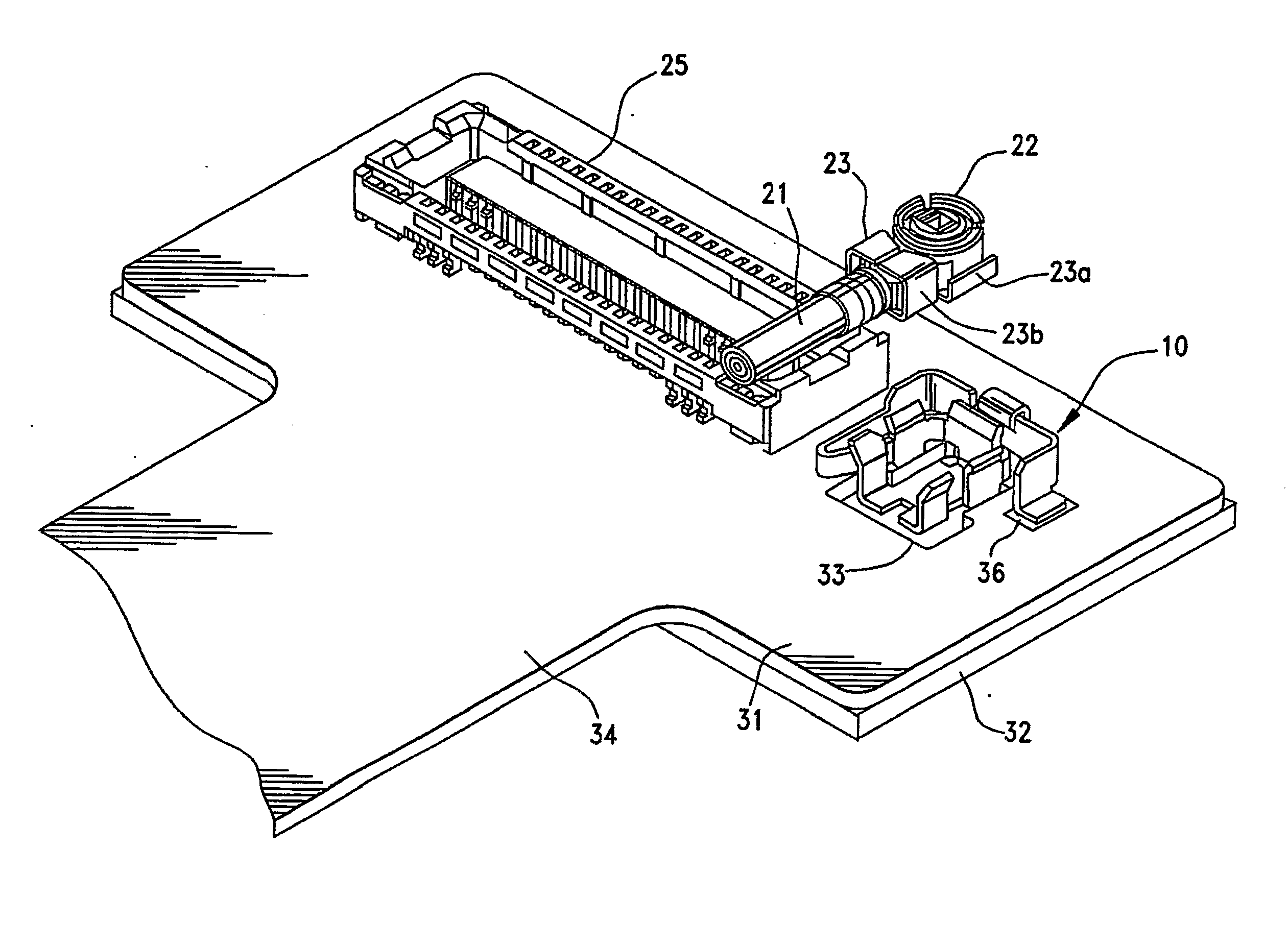
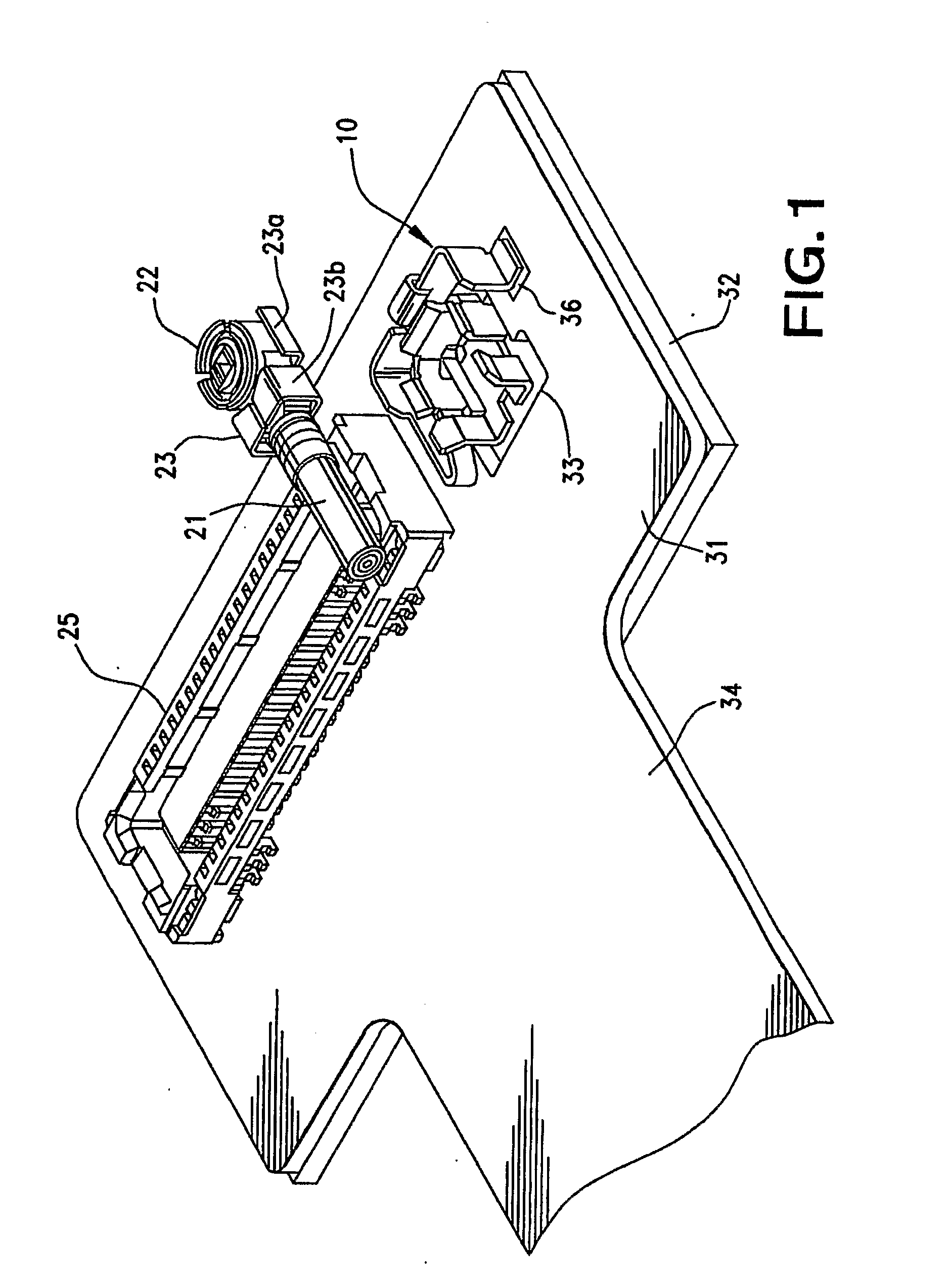
[0025]In FIG. 1, 10 designates a connector holder constructed according to the principles of the present invention, and which is secured to a connecting substrate 31 in equipment such as a mobile telephone. In the preferred embodiment, the equipment may be any kind of electronic equipment, including others than a mobile telephone, such as a personal computer, a PDA (personal digital assistant), a digital camera, a video camera, a music player, a game machine, or a car navigation system.

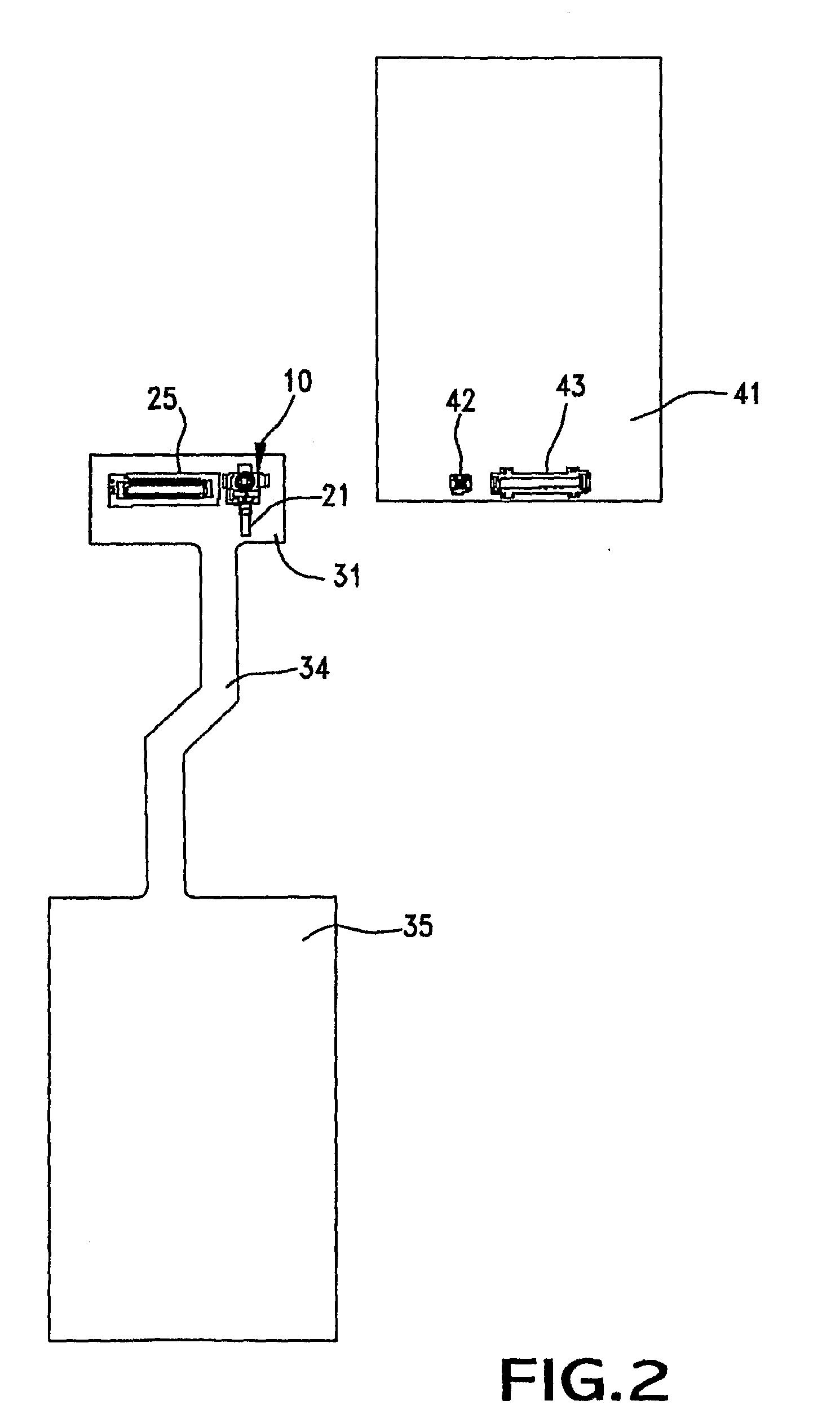
[0026]This description includes the assumption that the above-mentioned equipment has a casing that can be divided into a plurality of portions, each of the adjacent portions being rotatably connected. As an example a mobile telephone casing can be divided into a display part casing provided with a large display screen using a liquid crystal or LED display, and an operating ...


PUM


Abstract

A connector holder has a U-shaped frame and supports an internal connector-receiving part within the U-shaped frame. Guide pieces are provided that grip the ends of a connector and the cable to which the connector is attached. The connector-receiving part thereby floats inside of the U-shaped frame so as to be positioned accurately for mounting to an opposing connector.

Description

BACKGROUND OF THE INVENTION[0001]The present invention relates to a connector holder.[0002]Conventionally, when a cable is connected to a substrate in small electrical equipment, such as a mobile telephone, a connector that is connected to an end of the cable is fit into a base connector secured to a circuit board such as is shown in Japanese Utility Model Registration publication No. 2526329). FIG. 5 is a schematic cross-sectional view showing such a conventional connector holder[0003]In FIG. 5, 301 designates a connector that is connected to an end of a cable 302. For example, the connector 301 is fit into a board connector 303 secured to a substrate such as a printed circuit board 304 for use in electrical equipment such as automobile instruments, so that the cable 302 will be electrically connected to conductive traces on the substrate 304. In this case, the substrate connector 303 has an insulative female housing 305, and a connecting terminal 306 disposed within the housing 30...

Claims


Application Information

Patent Timeline
IPC IPC(8): H01R13/631H01R9/05
CPCH01R13/6315
Inventor MIZUMURA, AKINORISUZUKI, TERUHITO
Owner MOLEX INC
Why Eureka
Try Eureka