Scrivet fastener removal tool

a technology of fastener and scrivet, which is applied in the direction of metal-working hand tools, metal-working apparatus, pliers, etc., can solve the problems of time-consuming methods, damage to the structure surrounding the scrivet, and difficulty in removing the scrivet, etc., and achieves the effect of quick and efficient us

Inactive Publication Date: 2010-01-14
FULLER DAVID GRAHAM
View PDF39 Cites 3 Cited by
  • Summary
  • Abstract
  • Description
  • Claims
  • Application Information

AI Technical Summary

Benefits of technology

[0007]It is another object of the invention to provide a scrivet remover that does not damage the scrivet.
[0008]It is another object of the invention to provide a scrivet remover that does not cause foreign object damage.
[0009]It is another object of the invention to provide a scrivet remover that is quick and efficient to use.

Problems solved by technology

These methods are largely ineffective because the compression sleeve of the scrivet is still under stress as long as the central shank is still driven in, thereby causing interference stresses making removal of the scrivet difficult.
All of these methods are time consuming and may damage the structure surrounding the scrivet.
In other instances, the scrivet may be unrecoverable after dislodging the scrivet with a screwdriver or the like and the scrivet is many times destroyed during removal.
Scrivets are typically used for automotive and aircraft uses, and, in the instance of aircraft use, foreign object damage or loss of a scrivet within the aircraft can cause serious damage.
For automotive uses, the scrivet may incorporate an ornamental design and in these instances, damaging of the scrivet necessitates a replacement scrivet of the exact same design, usually at a substantial cost.

Method used


Image

  • Scrivet fastener removal tool
  • Scrivet fastener removal tool
  • Scrivet fastener removal tool

Examples


Embodiment Construction

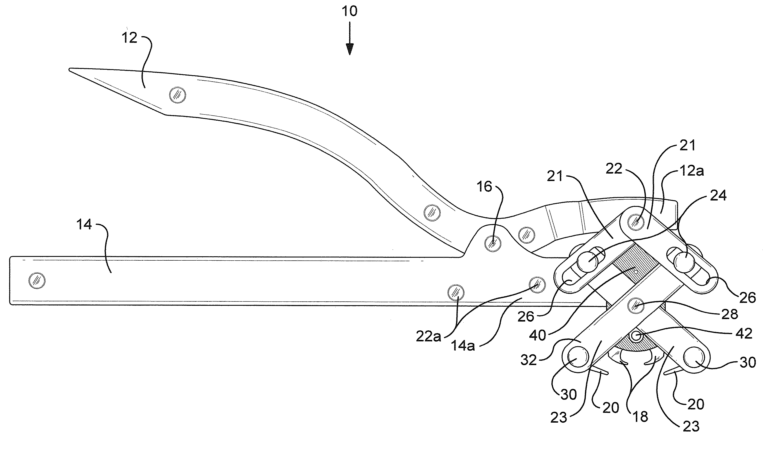
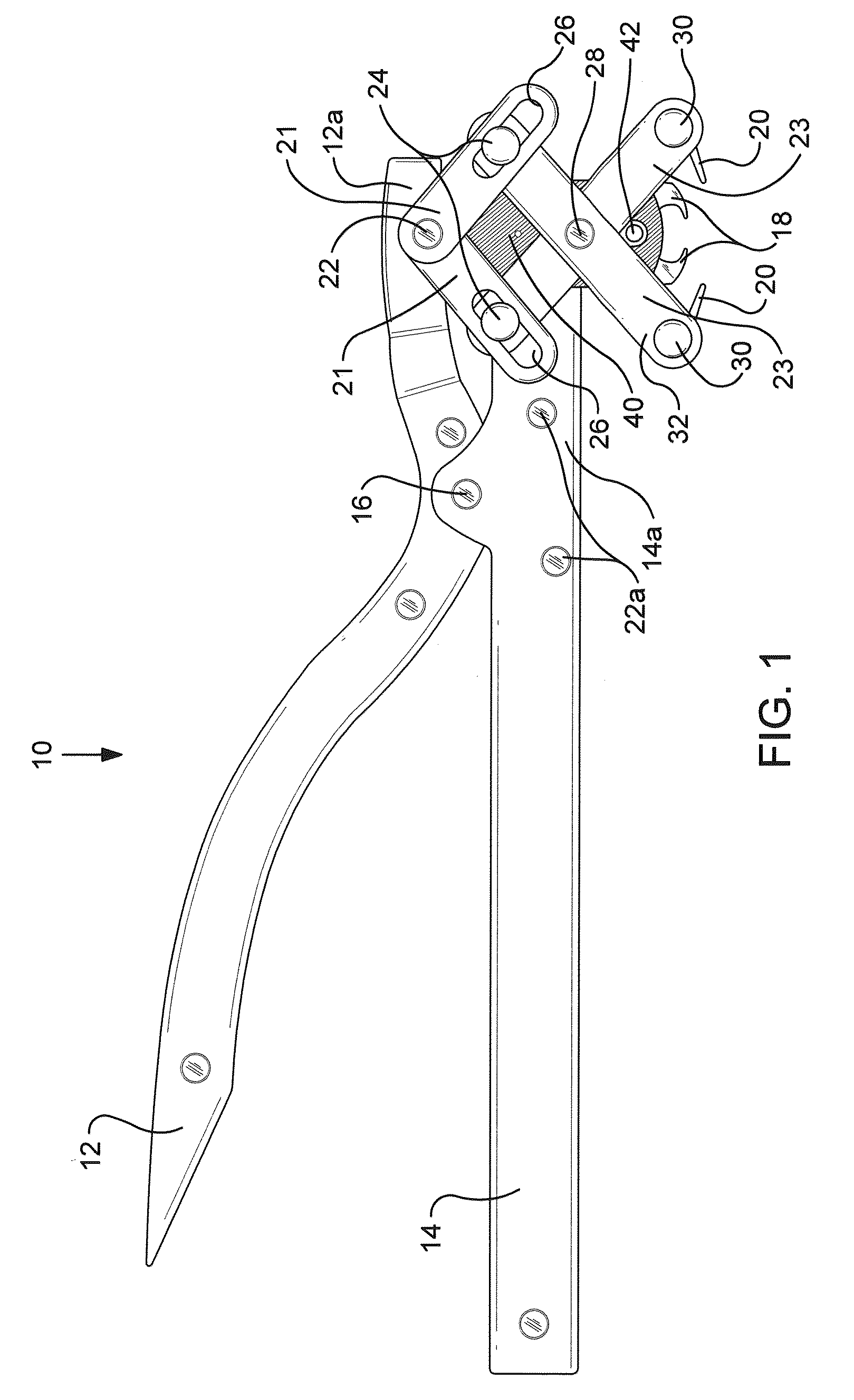
[0024]Referring now specifically to the drawings where like elements are represented by like referenced numerals, a scrivet fastener remover tool 10 is generally shown throughout FIGS. 1-5. The tool 10 is formed from a first handle 12 and a second handle 14 forming a pair of handles 12, 14 pivotally connected about a central connection 16. The pair of handles 12, 14 are configured such that upon a mechanical input like squeezing of the handles 12, 14, the pair of handles 12, 14 become closer together on the squeezing end and further apart on distal handle ends 12a and 14a.

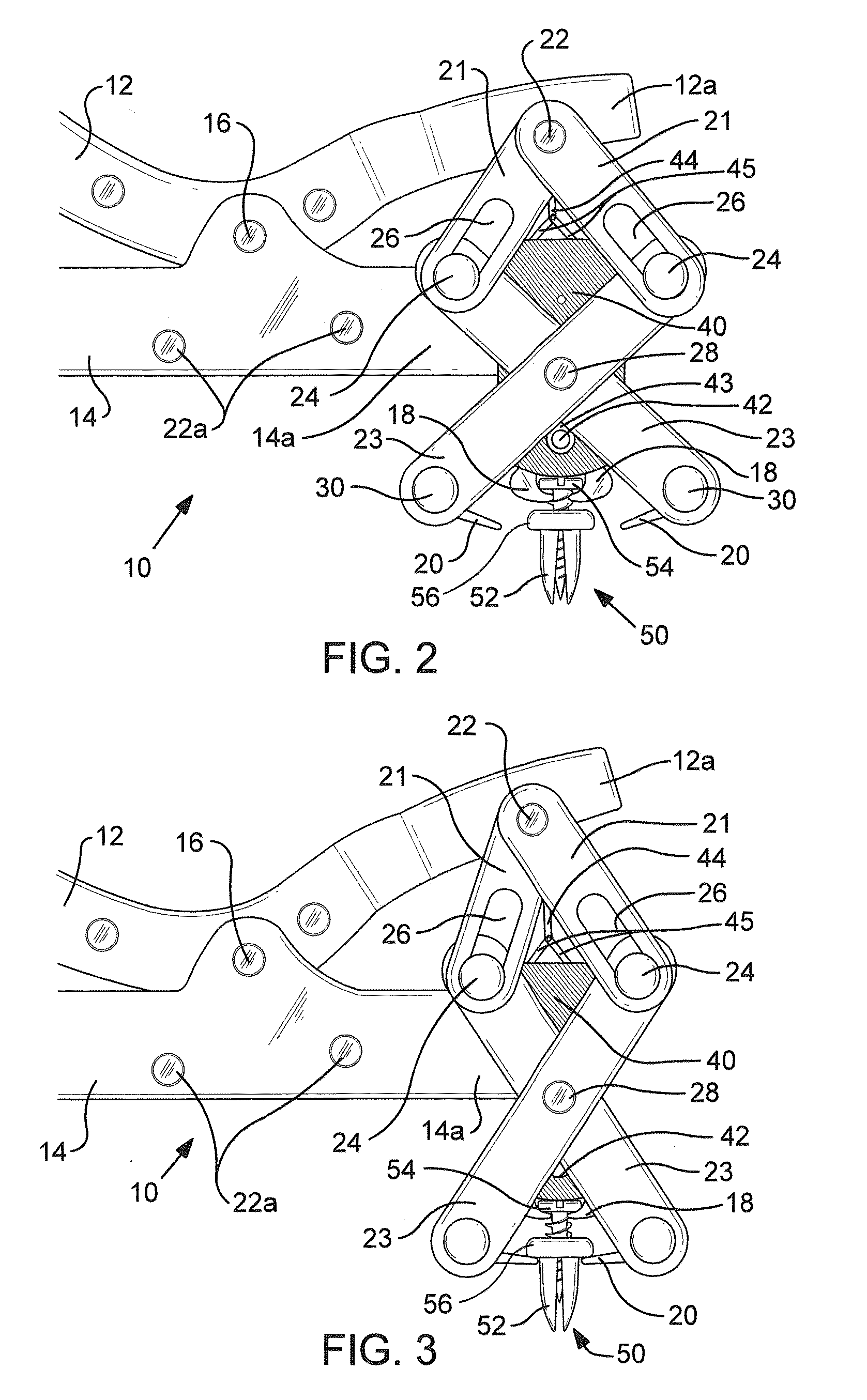
[0025]The handle 14 is connected to a connection block 40. The connection block 40 remains stationary relative to handle 14 because it is fixed to the distal end 14a of the second handle 14. Handle 12 is attached to a first linkage that includes a plunger 44 pivotally connected to a pair of linking members 45 forming a scissor like connection that is received within connecting block 40 and is pivotally connected w...


PUM

PropertyMeasurementUnit
areaaaaaaaaaaa
lengthaaaaaaaaaa
compression forcesaaaaaaaaaa

Abstract

A tool for removing a scrivet having a central shank and a compression sleeve having circumferentially spaced-apart wing elements is provided. The tool includes a first handle and a second handle, a first pair of gripping members configured to grip about the central shank of the scrivet, a second pair of gripping members configured to grip about the base of the scrivet, a first connecting mechanism attached to the first pair of gripping members, and a second connecting mechanism attached to the second pair of gripping members. The tool is configured such that the first pair of gripping members engages the central shank upon a first predetermined amount of movement of the handles and pull the central shank at a second predetermined amount of movement of the handles. A third predetermined movement of the handles causes the second pair of gripping members to grip the base of the scrivet.

Description

PRIORITY CLAIM[0001]This application claims priority to and hereby incorporates with reference the disclosure of U.S. Provisional Patent Application No. 61 / 079,815 filed on Jul. 11, 2008.TECHNICAL FIELD AND BACKGROUND OF THE INVENTION[0002]This application relates to a scrivet fastener removal tool. Scrivets are fasteners used to fasten two panels together and are typically made of a plastic material. The scrivet base rests against a first panel to be fastened to a second panel and is inserted into an aperture aligned between the two panels. The scrivet consists of a central shank configured to be driven into an expandable compression sleeve formed by circumferentially spaced-apart wing elements connected with a washer shaped base. The compression sleeve is of a smaller diameter than the central pin. The central shank is driven into the compression sleeve thereby causing expansion and holding the second panel against the first panel. In some instances, the scrivet may also include a...

Claims


Application Information

Patent Timeline
Patent Type & Authority Applications(United States)
IPC IPC(8): B25B9/00
CPCB25B7/00B25B7/02Y10T29/539B25B31/00B25B7/12
Inventor FULLER, DAVID GRAHAM
Owner FULLER DAVID GRAHAM
Why Eureka
Try Eureka