Transition with a linear flow path with exhaust mouths for use in a gas turbine engine

a gas turbine engine and linear flow technology, applied in the direction of machines/engines, liquid fuel engines, lighting and heating apparatus, etc., can solve the problems of reducing material properties, affecting the performance of the engine, so as to reduce the structural load on the mount, reduce excitation and stress, and eliminate damaging stresses

Active Publication Date: 2010-02-18
SIEMENS ENERGY INC
View PDF20 Cites 54 Cited by
  • Summary
  • Abstract
  • Description
  • Claims
  • Application Information

AI Technical Summary

Benefits of technology

[0020]This invention is directed to a transition duct for routing gas flow from a combustor to a turbine section of a turbine engine and eliminating damaging stresses created between conventional transitions and row one turbine vanes. The transition duct may have an axis that is generally linear with a generally linear flow path that combines the functions of a transition and row one turbine vanes. In such a configuration, the transition duct channels gases from a combustor basket to a downstream turbine blade assembly and accomplishes the task of redirecting the gases, thereby eliminating the need for row one vanes. The transition duct directs gases into the turbine assembly at the same incidence angle relative to the longitudinal axis of the engine and does not include any leading or trailing edges, and the problems inherent with e...

Problems solved by technology

The downstream wake can create vibrations in downstream turbine blades.
The use of first stage vanes to accelerate and turn the longitudinal gas flow in the circumferential direction present several challenges.
The forces and heat involved diminish material properties that can crack and otherwise damage the ...

Method used


Image

  • Transition with a linear flow path with exhaust mouths for use in a gas turbine engine
  • Transition with a linear flow path with exhaust mouths for use in a gas turbine engine
  • Transition with a linear flow path with exhaust mouths for use in a gas turbine engine

Examples


Embodiment Construction

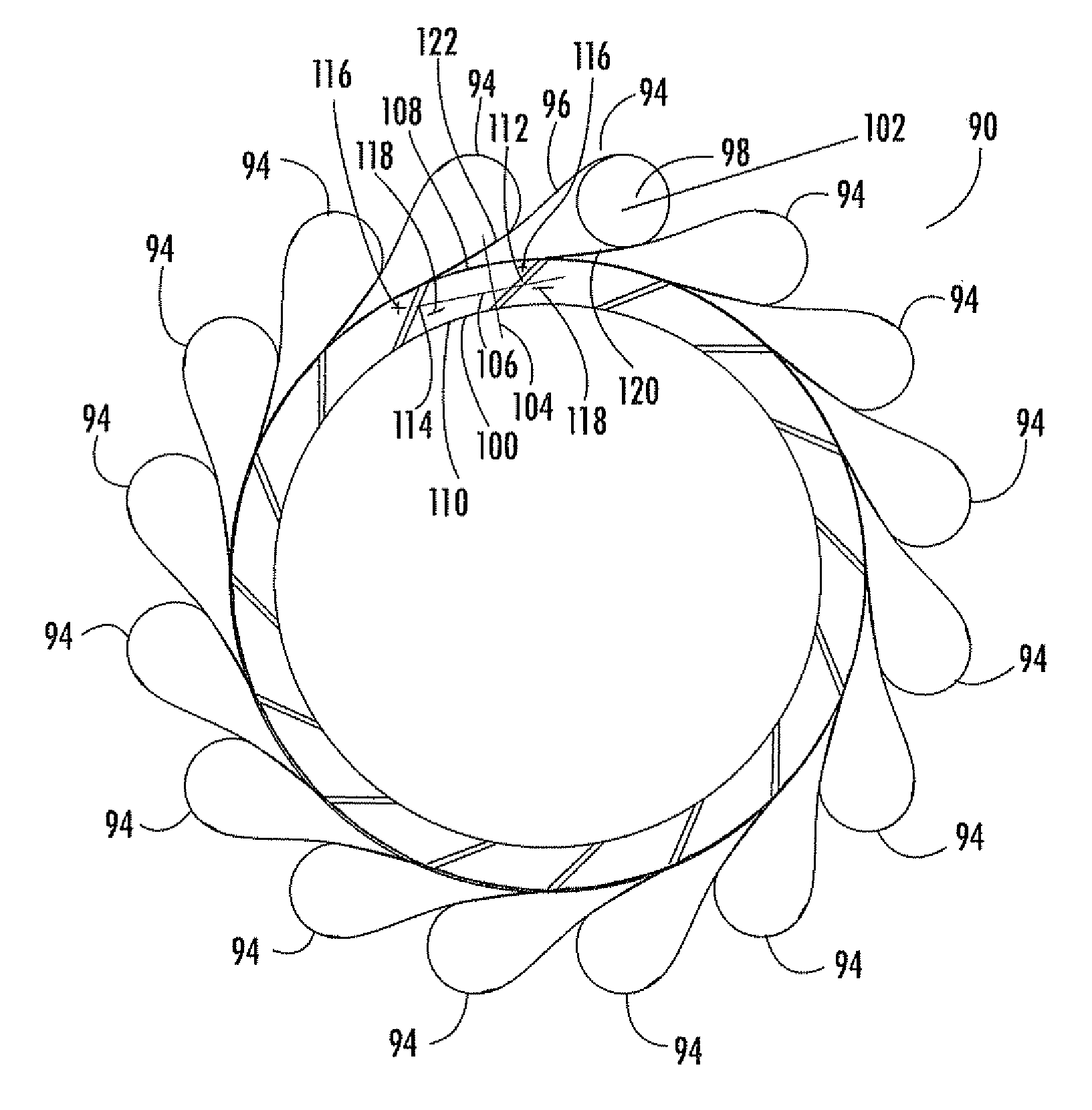
[0052]As shown in FIG. 4-12, this invention is directed to a transition duct 94 for routing gas flow from a combustor to a turbine section of a turbine engine. The transition duct 94 may be have an axis 130 that is generally linear. In such a configuration, the transition duct 94 channels gases from a combustor basket to a downstream turbine blade assembly and accomplishes the task of directing the gases, which has normally been accomplished with row one vanes. Thus, the transition duct 94 eliminates the need for row one vanes. The transition duct 94 may also be configured to include an outlet 100 with side surfaces 112, 114 that is configured to reduce downstream wake thereby resulting in reduced vibration in downstream turbine vanes. As such, the outlet 100 reduces inefficiencies caused by the combustor gases exiting the transition duct 94.

[0053]As shown in FIGS. 4, 5 and 7, the transition ducts 94 may be positioned in an annular array 90, as shown without surrounding turbine comp...


PUM


Abstract

A transition duct for routing a gas flow from a combustor to the first stage of a turbine section in a combustion turbine engine is disclosed. The transition duct may have an internal passage extending between an inlet to an outlet. An axis of the transition duct body may be generally linear such that gases expelled from the transition duct body flow in a proper direction into the downstream turbine blades. The linear transition duct may include an outlet with exhaust mouths that are configured such that sides of the transition duct are coplanar with adjacent transition ducts, thereby eliminating destructive turbulence between adjacent, linear transition ducts.

Description

FIELD OF THE INVENTION[0001]This invention is directed generally to gas turbine engines, and more particularly to transition ducts for routing gas flow from combustors to the turbine section of gas turbine engines.BACKGROUND OF THE INVENTION[0002]Referring to FIG. 1, there is shown a cross-section through a portion of a combustion turbine 10. The major components of the turbine are a compressor section 12, a combustion section 14 and a turbine section 16. A rotor assembly 18 is centrally located and extends through the three sections. The compressor section 12 can include cylinders 20, 22 that enclose alternating rows of stationary vanes 24 and rotating blades 26. The stationary vanes 24 can be affixed to the cylinder 20 while the rotating blades 26 can be mounted to the rotor assembly 18 for rotation with the rotor assembly 18.[0003]The combustion section 14 can include a shell 28 that forms a chamber 30. Multiple combustors, for example, sixteen combustors (only one combustor 32 o...

Claims


Application Information

Patent Timeline
IPC IPC(8): F02C7/00
CPCF01D9/023F01D9/041Y02T50/675Y02T50/673Y02T50/671Y02T50/60
Inventor CHARRON, RICHARDSNYDER, GARY
Owner SIEMENS ENERGY INC
Why Eureka
Try Eureka