Display device and display drive method

Active Publication Date: 2010-02-25
JOLED INC
View PDF7 Cites 4 Cited by
  • Summary
  • Abstract
  • Description
  • Claims
  • Application Information

AI Technical Summary

Benefits of technology

[0019]Here, it is possible to prevent the increase of the gate potential and the source potential and to perform more accurate threshold correction by cutting off the drive transistor in periods after the threshold correction operations (after-correction periods) to suppress leak current. On the other hand, it is possible to allow the voltage between the gate and the source of the drive transistor to converge to the threshold voltage earlier by positively using the leak current. That is, the threshold correction operation can be accelerated.
[0020]In the embodiments of the invention, both accuracy and quickness in the threshold correction operation are realized by providing a period in which the drive transistor is cut off and a period in which the drive transistor is not cut off in plural after-correction periods.
[0021]According to the embodiments of the invention, when performing threshold correction in the time division manner, a period in which drive transi

Problems solved by technology

The former has problems such that it is difficult to realize a large-sized as well as high-definition display though

Method used


Image

  • Display device and display drive method
  • Display device and display drive method
  • Display device and display drive method

Examples


first embodiment

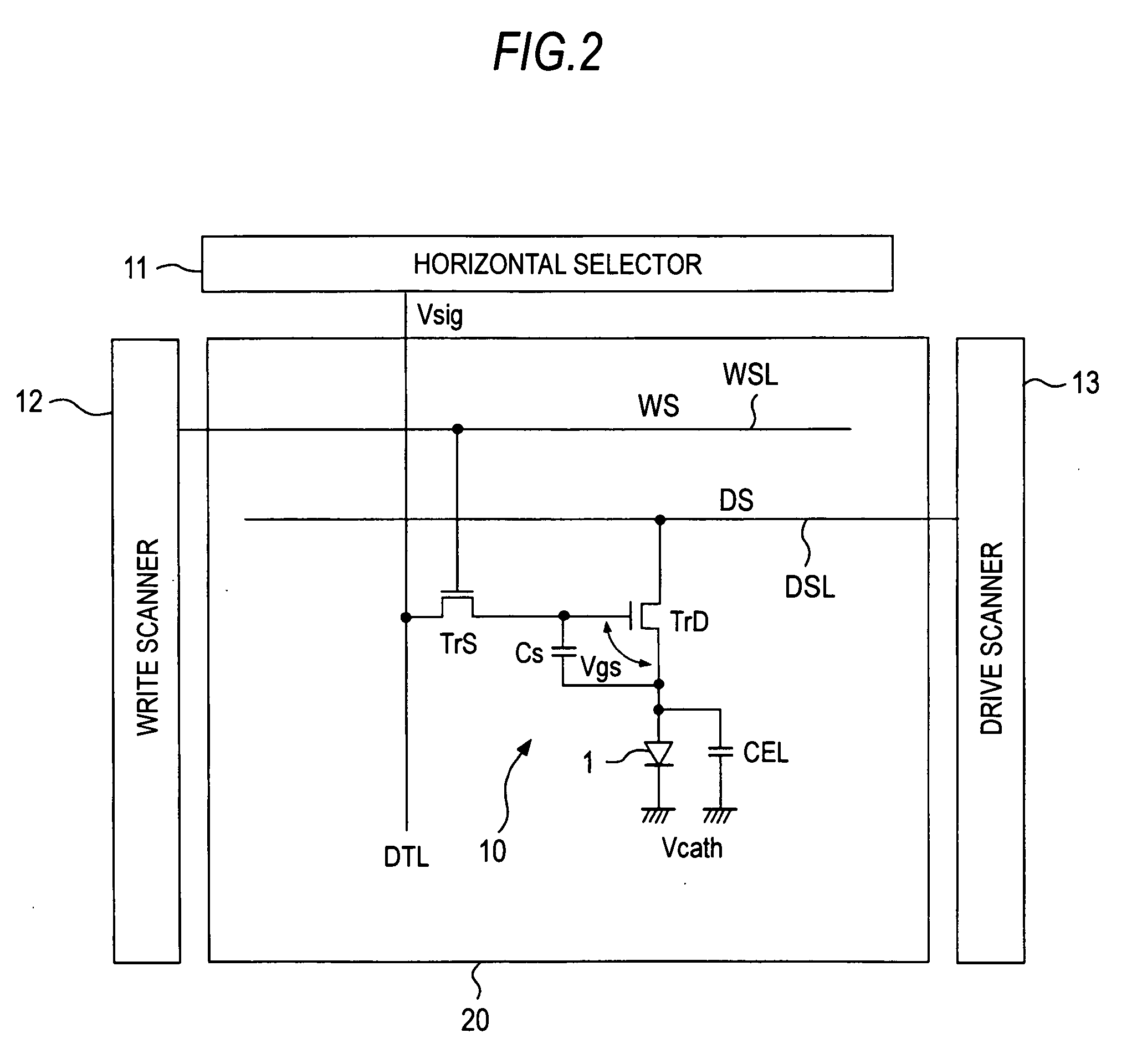
[0077]Since the drain current changes also by the mobility of the drive transistor TrD, image quality is reduced by variation of the mobility of the drive transistor TrD at each pixel circuit 10, the source potential Vs can be obtained according to the degree of mobility of the drive transistor TrD by the mobility correction, as a result, the source potential Vs is adjusted to obtain the voltage Vgs between the gate and the source which absorbs variation of the mobility of the drive transistor TrD in each pixel circuit 10, therefore, reduction of image quality due to the variation of mobility is also prevented.[0078]3. Pixel Circuit Operation as the Invention

[0079]As described above, as a pixel circuit operation of one cycle, the Vth cancel operation is performed in the divided manner plural times. The reason that the Vth cancel operation is performed plural times in the time division manner is because there is a request for the high frequency in the display device.

[0080]As the fram...

second embodiment

[0126]As described above, if the drive transistor TrD is cut off every time in plural after-correction periods in order to realize the accuracy of the threshold correction operation, the power pulse DS is made to be the intermediate potential V2 every time in plural after-correction periods, when following the cut-off control method of FIG. 5. This causes frequent change of the pulse level in the power control line WSL within one cycle, therefore, so-called power fluctuation tends to occur, which narrows an operation margin of each power supply. However, the power pulse DS is made to be the intermediate voltage V2 only in the first after-correction period t5 in the embodiment, therefore, it is not necessary to change the pulse level frequently in the power control line WSL. According to this, the operation margin of the power supply is not considerably narrowed and there is no disadvantage on design.[0127]4. Pixel Circuit Operation as the Invention

[0128]The pixel circuit operation a...


PUM


Abstract

A display device includes: a pixel array including pixel circuits arranged in a matrix state, in which each pixel circuit has a light emitting element, a drive transistor, and a storage capacitor storing a threshold voltage of the drive transistor and an inputted signal value; a threshold correction operation means for performing a threshold correction operation plural times, which allows the storage capacitor to store the threshold voltage of the drive transistor before giving the signal value to the storage capacitor; and a cut-off control means for allowing the drive transistor to be cut off in at least one after-correction period and for allowing the drive transistor not to be cut off in at least one after-correction period in plural after-correction periods which are periods after the plural threshold correction operation periods.

Description

BACKGROUND OF THE INVENTION[0001]1. Field of the Invention[0002]The invention relates to a display device including a pixel array in which pixel circuits are arranged in a matrix state and a display drive method thereof, and relates to, for example, a display device using an organic electroluminescence element (organic EL element) as a light emitting element.[0003]2. Description of the Related Art[0004]An image display device in which an organic EL element is used in a pixel is developed, for example as shown in JP-2003-255856 and JP-2003-271095 (Patent Documents 2 and 3). Since the organic EL element is a self-luminous element, it has advantages such that visibility of images is higher than, for example, a liquid crystal display, a backlight is not necessary and response speed is high. The luminance level (tone) of each light emitting element can be controlled by a value of current flowing therein (so-called current-control type).[0005]The organic EL display has a passive matrix ty...

Claims


Application Information

Patent Timeline
IPC IPC(8): G06F3/038
CPCG09G3/3233G09G2320/043G09G2300/0842
Inventor YAMASHITA, JUNICHIUCHINO, KATSUHIDE
Owner JOLED INC
Why Eureka
Try Eureka