Lamp shape structure

a technology of lamp shade and shape structure, applied in the field of lamp shade, can solve the problems of uneven or damaged light-reflective coating on the reflective sheet, large volume, heavy etc., and achieve the effect of improving the reflectivity of the lamp shade structure, power consumption, and reducing the effect of weigh

Inactive Publication Date: 2010-03-18
KOCAM INT
View PDF4 Cites 1 Cited by
  • Summary
  • Abstract
  • Description
  • Claims
  • Application Information

AI Technical Summary

Benefits of technology

[0008]In view of the foregoing shortcomings of the conventional lamp shade structure having a smaller thickness occurred at bent positions of a reflective sheet after a stamping and molding process takes place and affecting the reflecting efficiency of the lamp shade adversely, as well as having the difficulty of stamping the reflective sheet with a smooth arc cross-sectional shape, the inventor of the present invention based on years of experience in the related industry to conduct extensive researches and experiments, and finally designed and developed a lamp shade structure in accordance with the present invention to overcome the aforementioned shortcomings, and the invention can increase the reflecting efficiency and the quality of the LCD of the lamp shade structure.
[0009]Therefore, it is a primary objective of the present invention to provide a lamp shade structure comprising a metal hood, an adhesive layer and a reflective sheet, and the lamp shade structure is applied to a liquid crystal display (LCD) backlight module, wherein after the metal hood is bent, a containing space is formed at an internal side of the metal hood, and the adhesive layer has an adhesiveness and is disposed between the metal hood and the reflective sheet, and the cross-section of the reflective sheet is substantially an arc shape, such that the reflective sheet can be attached in the containing space by the adhesiveness of the adhesive layer. Since the cross-section of the reflective sheet is in an arc shape, therefore the reflecting efficiency of the lamp shade structure can be improved effectively.
[0010]Another objective of the present invention is to avoid stamping the workpiece composed of the metal sheet, adhesive layer and reflective sheet since the cross-section of the reflective sheet is in an arc shape, and the adhesive layer is attached to the bent metal hood, and thus the invention can prevent the thickness of the bent position from becoming thinner due to a deformation formed at the bent position after the reflective sheet is stamped and molded. Therefore, the present invention can improve the uneven thickness occurred at each position of the reflective sheet of the lamp shade produced by the conventional molding process, so as to increase the reflecting efficiency of the lamp shade structure.
[0011]A further objective of the present invention is to provide a protecting film on a side of the reflective sheet opposite to the metal hood, so as to prevent any unintentional scratch to the reflective sheet while the molded lamp shade structure is being transported, and reduce the chance of having a low reflecting efficiency of the lamp shade structure, and extend the using life of the lamp shade structure effectively.

Problems solved by technology

Conventional display products (such as televisions and monitors, etc) generally use a cathode ray tube (CRT) to achieve the display effect, however, the conventional CRT display devices are usually existing the problems of having large volume, heavy weight and power-consuming.
In addition, when the deformation occurs at the bent position of the reflective sheet 14, the surface at the bent position or near the bent position will be pressed or extended, such that the light-reflective coating on the reflective sheet 14 will become uneven or damaged, and the uneven or damaged light-reflective coating will affect the reflecting efficiency of the lamp shade adversely.
Besides, when the lamp shade is stamped into a cross-sectional shape with many bends, the thickness of the reflective sheet 14 will become uneven, and many thinner spots will result and cause an increased defective rate of the LCD products that adopt the conventional lamp shade structure.

Method used


Image

  • Lamp shape structure
  • Lamp shape structure
  • Lamp shape structure

Examples


Embodiment Construction

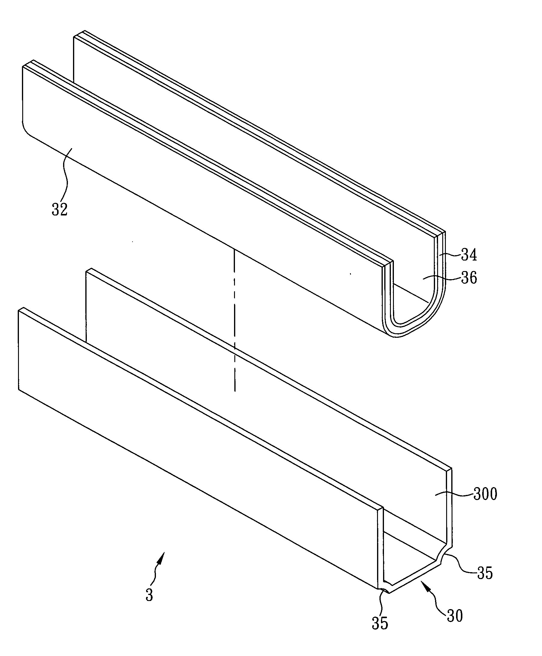
[0016]With reference to FIG. 3 for a liquid crystal display (LCD) lamp shade structure applied to an LCD backlight module, the lamp shade structure 3 comprises a metal hood 30, an adhesive layer 32 and a reflective sheet 34, wherein the metal hood 30 is formed by bending a metal sheet with a cross-sectional shape, and the cross-sectional shape of a reflective sheet 34 is substantially an arc shape, and the adhesive layer 32 is attached between the metal hood 30 and the reflective sheet 34 for sticking the metal hood 30 and the reflective sheet 34 together to form the lamp shade structure 3.

[0017]In a preferred embodiment of the present invention as shown in FIG. 3, a lamp shade structure 3 comprises a metal hood 30, an adhesive layer 32 and a reflective sheet 34, wherein the metal hood 30 is formed by bending a stamped metal sheet into a cross-sectional shape according to the shape of a casing (not shown in the figure) of an LCD required to be installed to the lamp shade structure 3...


PUM


Abstract

A lamp shade structure applied to a liquid crystal display backlight module includes a metal hood, an adhesive layer and a reflective sheet, wherein the metal hood is formed by bending a metal sheet into a cross-sectional shape and has a containing space formed at an internal side of the metal hood, the cross-section of the reflective sheet is in an arc shape, and a side of the reflective sheet is attached to the containing space through the adhesive layer. Since the cross-section of the reflective sheet is in an arc shape, therefore the present invention can improve the reflecting efficiency of the lamp shade structure effectively.

Description

FIELD OF THE INVENTION[0001]The present invention relates to a lamp shade, more particularly to a lamp shade structure applied to a liquid crystal display (LCD) backlight module and including a reflective sheet with an arc-shaped cross-section for increasing reflecting efficiency of the lamp shade.BACKGROUND OF THE INVENTION[0002]Conventional display products (such as televisions and monitors, etc) generally use a cathode ray tube (CRT) to achieve the display effect, however, the conventional CRT display devices are usually existing the problems of having large volume, heavy weight and power-consuming. As high technologies keeping on advancing, the conventional way of manufacturing display products by using CRT is gradually replaced by liquid crystal display (LCD) panel under the reasons that LCD panel products (including televisions, monitors, and notebook computers, etc) are lighter, thinner, shorter and smaller than the conventional CRT products, such that users can move the LCD ...

Claims


Application Information

Patent Timeline
Patent Type & Authority Applications(United States)
IPC IPC(8): F21V7/00
CPCG02F1/133605G02F1/133604
Inventor CHEN, TSAN-JUNG
Owner KOCAM INT
Why Eureka
Try Eureka