System and method for measuring antenna radiation pattern in fresnel region based on phi-variation method

a radiation pattern and antenna technology, applied in the direction of direction finders, instruments, transmission monitoring, etc., can solve the problems of inability to secure secrets, interference and errors in conventional communication services, sensitive open-air measurement methods, etc., and achieve the effect of large antenna aperture and additional cos

Inactive Publication Date: 2010-03-25
ELECTRONICS & TELECOMM RES INST
View PDF5 Cites 16 Cited by
  • Summary
  • Abstract
  • Description
  • Claims
  • Application Information

AI Technical Summary

Benefits of technology

[0018]The present invention can be applied to a popular antenna radiation pattern measuring system, i.e., a far-field measurement system having a positioner which can rotate an antenna into phi direction and theta direction, and thus additional cost which occurs in the general chamber not satisfying the far-field condition due to the large antenna aperture, can be reduced.
[0019]Also, in the present invention, since angles of one antenna, which is the target antenna, are not varied upward and downward, the other antenna, which is the reference antenna, does not require high-directivity, and the standard antenna can be utilized.

Problems solved by technology

However, the open-air measurement method is sensitive to the weather, and occurs interferences and errors from conventional communication services.
In addition, a military antenna and a security antenna can be exposed to a spy satellite, so that secrets cannot be secured.
However, the compact range method requires a hard-adherence and high-price reflector antenna.
Also, in a low frequency band, i.e., hundreds MHz, size of the reflector is large so that installation and maintenance of the reflector are difficult, and in a high frequency band, i.e., over 100 GHz, the reflector is hard to be manufactured due to μm fabrication errors.
However, mechanical instruments operating the probe should be precise, thus a lot of financial resources are needed.
However, the Fresnel region measurement method has several disadvantages in actual measurement environment.
In addition, when a large-size antenna is inclined downward in order to change angles of the large-size antenna having tens of kilograms (Kg), safety concerns such as a breakdown can occur due to weight of the antenna and the positioner.
Moreover, when the angles of the antenna are varied upward and downward, undesirable reflection waves reflected from absorber adhered to a flat surface and a ceiling surface can be received, and thus measurement errors occur.
Therefore, utilization of a standard antenna is low and it is not efficiency.

Method used


Image

  • System and method for measuring antenna radiation pattern in fresnel region based on phi-variation method
  • System and method for measuring antenna radiation pattern in fresnel region based on phi-variation method
  • System and method for measuring antenna radiation pattern in fresnel region based on phi-variation method

Examples


Embodiment Construction

[0025]The advantages, features and aspects of the invention will become apparent from the following description of the embodiments with reference to the accompanying drawings, which is set forth hereinafter, and thus the invention will be easily carried out by those skilled in the art to which the invention pertains. Also, when it is considered that detailed description on a related art may obscure the points of the present invention unnecessarily in describing the present invention, the description will not be provided herein. Hereinafter, specific embodiments of the present invention will be described with reference to the accompanying drawings.

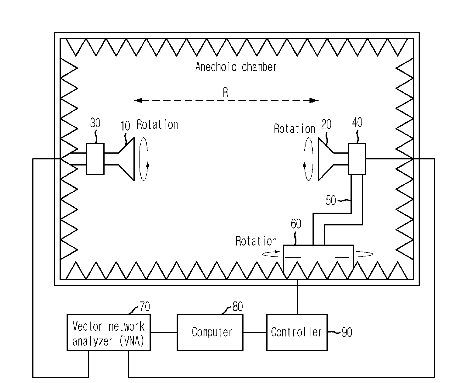
[0026]FIG. 1 is a block diagram illustrating a system for measuring an antenna radiation pattern in a Fresnel region based on a phi-variation method in accordance with an embodiment of the present invention.

[0027]As shown in FIG. 1, the system for measuring the antenna radiation pattern in the Fresnel region based on the phi-variation metho...


PUM


Abstract

Provided is a system and method for measuring an antenna radiation pattern in a Fresnel region based on a phi-variation method. The system includes a rotator for changing angles of a reference antenna and a target antenna; a vector network analyzer for obtaining radiation pattern data in accordance with transmission/reception radio frequency (RF) signals between the reference antenna and the target antenna; a measurement unit for calculating a far-field radiation pattern based on the radiation pattern data received from the vector network analyzer; and a controller for controlling the rotator according to a measurement angle transmitted from the measurement unit.

Description

TECHNICAL FIELD[0001]The present invention relates to a system and method for measuring an antenna radiation pattern in a Fresnel region based on a phi-variation method; and, more particularly, to a system and method for measuring an antenna radiation pattern in a Fresnel region based on a phi-variation method, which can measure a far-distance radiation pattern in the Fresnel region of an anechoic chamber based on the phi-variation method and a far-field measurement system.[0002]This work was supported by the Ministry of Science and Technology [“Development of Antenna Measurement System Technology”].BACKGROUND ART[0003]Size of a reflector antenna for a satellite or an array antenna having a plurality of unit antennas is more than ten times that of the unit antenna.[0004]Therefore, a minimum distance Rfar between a source antenna and a measurement antenna must satisfy Rfar=2×L2 / λ. Herein, L is a length of aperture of the measurement antenna, and λ is a wavelength of operation frequen...

Claims


Application Information

Patent Timeline
Patent Type & Authority Applications(United States)
IPC IPC(8): G01R29/10
CPCG01R29/105G01R29/0892G01S3/06H01Q11/04H04B7/02
Inventor OH, SOON-SOOCHO, YONG-HEEYUN, JE-HOONKIM, JOUNG-MYOUNMOON, JUNG-ICK
Owner ELECTRONICS & TELECOMM RES INST
Why Eureka
Try Eureka