Transmission screen for stereoscopic images

a stereoscopic image and transmission screen technology, applied in the field of transmission screen, can solve the problems of less than 20% transmission efficiency, unfavorable three-dimensional viewing, and inability to implement stereoscopic images, and achieve the effect of increasing brightness and clarity

Inactive Publication Date: 2010-03-25
CHOI HAE YONG
View PDF5 Cites 0 Cited by
  • Summary
  • Abstract
  • Description
  • Claims
  • Application Information

AI Technical Summary

Benefits of technology

[0049]In this way, polarized images are transmitted and imaged while maintaining the polarization degree, so that the three-dimensional effect is increased by two times.
[0050]According to the present invention, the incident surface 2 having a gloss surface enables projected images to be incident thereto by an amount of 2 times more than conventional screens. The transmission layer 4 havin...

Problems solved by technology

Conventional transmission screens having transmission layers are transmission screens through which general images are transmitted, and include a medium having a refractive index, diffusion material within the medium, and diffusion material on the surface of the medium, so that in the course of transmitting polarized images, the images are not only diffused, but also the degree of polarization of the polarized images is diffused, and thus the implementation of stereoscopic images is impossible.
However, there are disadvantages to such scenes in that deformation of the screen occurs due to climatic changes as time elapses and, more particularly, since the image displayed on a surface of the screen is diffused, the efficiency of transmission is less than 20%, the angle of polarization is diffused, and therefore the viewing angle becomes narrow, thereby making three-dimensional viewing uncomfortable.
For the above-described reasons, a screen having a thin film is not sui...

Method used


Image

  • Transmission screen for stereoscopic images
  • Transmission screen for stereoscopic images
  • Transmission screen for stereoscopic images

Examples


first embodiment

[0058]FIG. 3 is a cross-sectional view of components of an embodiment of the present invention.

[0059]FIG. 4(a) is a view describing the effect of FIG. 3.

[0060]FIG. 4(b) is a view describing a state in which left and right images are imaged (displayed) on a screen.

[0061]The screen substrate of FIG. 3 according to the present invention has a refractive index s of 1.49.

[0062]The transmissivity p of the material is 90% to 95% by itself, but may be 85% when pigment having the color of smog on the order of 1-4% is included, so that the entire color of the screen substrate become the color of smog, thereby making a color transmitted from the rear surface more clear with respect to external (ambient) light.

[0063]When the rear surface of the screen substrate becomes dark, the clarity thereof increases with respect to external (ambient) light by two times or more.

[0064]Furthermore, the incident surface 2 of the screen substrate 1 has a gloss surface so that 85% of the images of right and left...

second embodiment

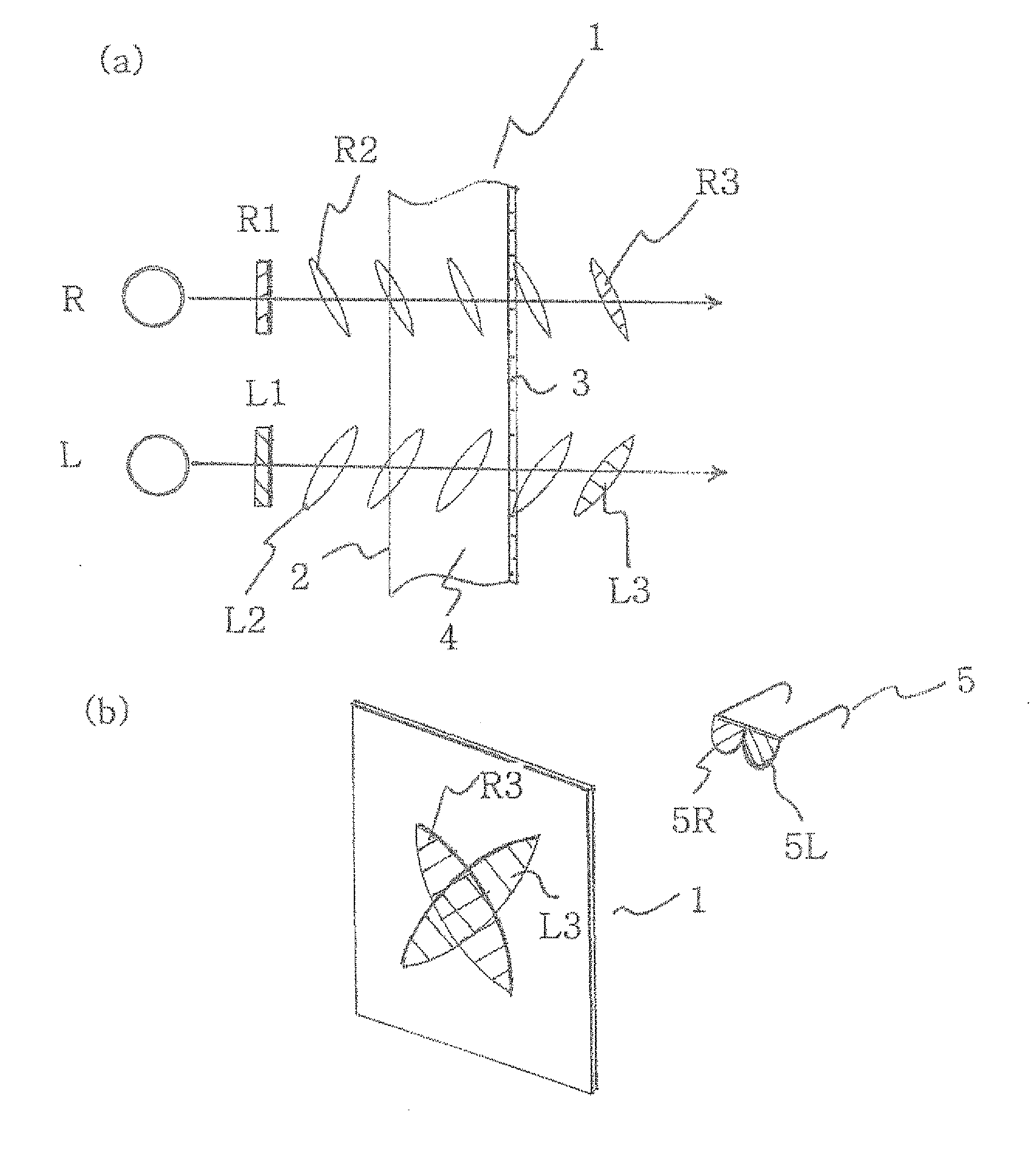
[0067]As illustrated in FIG. 5, the present invention can include a polarization plate 6, having symmetric angles with respect to each other in upper and lower directions, on the imaging surface of the screen substrate 1; that is, the front surface of the imaging surface 2, and can define curved vertical lines 7 having the form of a curved surface on the front surface thereof.

[0068]In this case, the refractive index s, and transmissivity p of the curved vertical line 7, and surface particle size of the incident surface 2 are identical to those of the screen substrate 1 according to the present invention.

third embodiment

[0069]The present invention may be further characterized in that the transmission layer 4 transmits polarized images without loss and at the same time, general images may be projected more brightly than conventional screens.

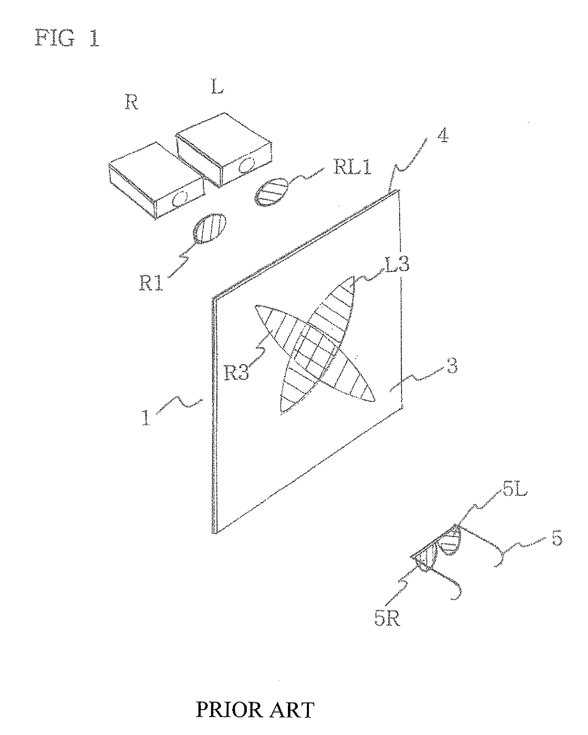
[0070]That is, in FIG. 1, when among the left and right projectors p1 and p2, for example, the left projector p1 is selected, and the left polarization filter L1 in front thereof is moved in an upward or downward direction, images are projected onto a screen without the polarization filter and general images will be projected. Therefore, general images can be projected, and, if needed, general images or stereoscopic images may be selectively projected.

[0071]In such case, general images are viewable by viewers with transmissity and resultant light twice that of a conventional screen, thereby making such images twice as clear as compared to a conventional screen.

[0072]Therefore, the screen of the present invention is usable both as a high-definition transmission sc...


PUM


Abstract

A transmission type screen for stereoscopic images having a transmission layer includes an incident surface having a gloss surface, a transmission layer having a refractive index less than 1.55, a transmissivity more than 60%, and an imaging surface having surface particle sizes of 40 to 400 mesh that avoids a hot spot. The imaging surface is formed on the final surface through which images are transmitted, so that the components operate in an organic fashion with respect to each other. The polarization degree of stereoscopic images is maximized thereby increasing the three-dimensional effect and the transmissivity, and enables viewers to view images clearly several times better than with a conventional screen.

Description

BACKGROUND OF THE INVENTION[0001]1. Field of the Invention[0002]The present invention relates, in general, to a transmission type screen, and, more particularly, to a transmission screen for displaying stereoscopic images and which has a transmission layer for transmitting images while maintaining the degree of polarization thereof. The screen also is suitable for both stereoscopic images and general images with improved definition of the images.[0003]2. Description for the Related Art[0004]A transmission screen is a screen on which images are projected from the rear side of the screen and which allows a user to view images displayed on the front side of the screen.[0005]Conventional transmission screens having transmission layers are transmission screens through which general images are transmitted, and include a medium having a refractive index, diffusion material within the medium, and diffusion material on the surface of the medium, so that in the course of transmitting polarize...

Claims


Application Information

Patent Timeline
IPC IPC(8): G03B21/56G02B30/25
CPCG03B21/62G02B27/26G02B30/25H04N13/30
Inventor CHOI, HAE-YONG
Owner CHOI HAE YONG
Why Eureka
Try Eureka