Slot-in optical disk drive

a slot-in technology, which is applied in the direction of information storage, instruments, data recording, etc., can solve the problems of difficult to reduce unsolved problems in the positioning device of the conventional slot-in optical disk drive, and complicated linkage mechanisms. , to achieve the effect of reducing the thickness of the positioning device, reducing the thickness of the optical disk drive, and strengthening the linkage mechanism of the positioning devi

Inactive Publication Date: 2010-03-25
QUANTA STORAGE INC
View PDF4 Cites 0 Cited by
  • Summary
  • Abstract
  • Description
  • Claims
  • Application Information

AI Technical Summary

Benefits of technology

[0008]Another object of the invention is directed to a slot-in optical disk drive. A linkage mechanism is single layer. Therefore, the thickness of the positioning device is decreased so that the thickness of the optical disk drive is reduced as well.
[0009]A further object of the invention is directed to a slot-in optical disk drive. The linkage mechanism of the positioning device is strengthened. As a result, the positioning device can be made of plastic material so that the sliding friction between parts is reduced. The weight and the manufacturing cost are lowered accordingly.

Problems solved by technology

However, the guiding rods and linkage mechanisms of the slot-in optical disk drive have to guide the disk continuously during the whole insertion or ejection process.
As a result, the linkage mechanisms are complicated and hard to assemble.
Furthermore, it is difficult to reduce the thickness of the optical disk drive because the mechanisms overlap with each other.
Therefore, there are still unsolved problems in the positioning device of the conventional slot-in optical disk drive.

Method used


Image

  • Slot-in optical disk drive
  • Slot-in optical disk drive
  • Slot-in optical disk drive

Examples


Embodiment Construction

[0021]A preferred embodiment is described as follows with reference to the accompanying drawings to illustrate the technical means adopted by the present invention to achieve above object and the effect thereof.

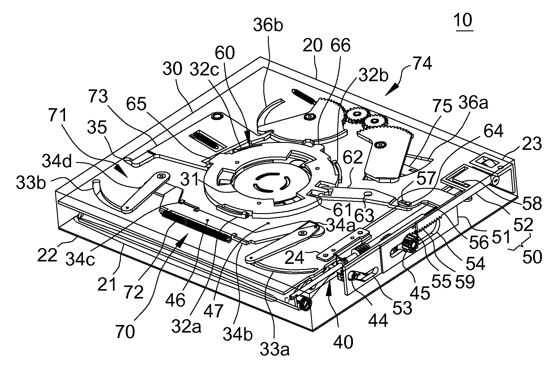
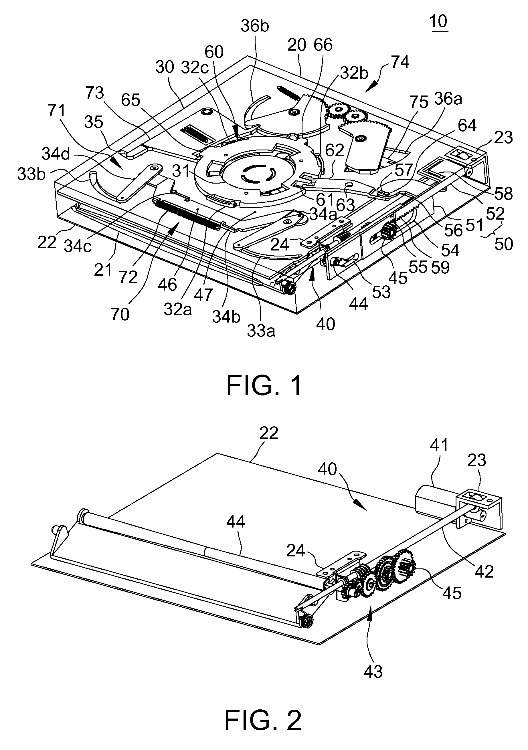
[0022]Please refer to FIG. 1, which illustrates a slot-in optical disk drive 10 of the present invention. The slot-in disk drive 10 mainly includes a casing 20, a base plate 30, a transmission unit 40, a linkage plate set 50, a clamping unit 60 and a positioning device 70. The casing 20 is hollow. An opening 21, which is a long slit, is formed on the front so that a disk can be inserted or ejected. The bottom of the casing 20 is a bottom plate 22. A fastening bracket 23 is disposed on the bottom plate 22 on the rear of the casing 20. A bracket 24 is disposed on the bottom plate 22 and protrudes upwards from a side of the bottom plate 22.

[0023]A base plate 30 is disposed in the casing 20 of the optical disk drive 10 and above the bottom plate 22. A disk is inserted or ejected ...


PUM

PropertyMeasurementUnit
elastic forceaaaaaaaaaa
sizeaaaaaaaaaa
sizesaaaaaaaaaa

Abstract

A slot-in type disk drive fastens a clamping unit with two protrusions around its periphery on the central hole of a base plate. A front positioning part utilizes a stick to link a front right positioning bar and a front left positioning bar to synchronously open or close. A locking rod has a limiting pin inserted into an arc slot on the side of the base plate, and protrudes a locking end from the rear end. A rear positioning part utilizes an idle gear to link rear right and rear left positioning bars to synchronously open or close. The locking end can insert a first or second positioning recess on the rear left positioning bar and a touch block of the locking rod leans against the first protrusion. A lever is disposed on the rear right positioning bar to link a linkage plate set by one end.

Description

[0001]This application claims the benefit of Taiwan application Serial No. 97136580, filed Sep. 23, 2008, the subject matter of which is incorporated herein by reference.BACKGROUND OF THE INVENTION[0002]1. Field of the Invention[0003]The invention relates in general to a slot-in optical disk drive, and more particularly to a slot-in optical disk drive using a positioning device to guide disks of different sizes to be inserted or ejected.[0004]2. Description of the Related Art[0005]Optical disk drives are generally categorized as tray type and slot-in type according to the way the disk is inserted. A tray type optical disk drive uses a tray to hold the disk, so that the tray is slid in or out the disk drive for inserting or ejecting the disk. As to the slot-in optical disk drives, the disk is directly inserted in the slot of the optical disk drive, and a slot-loading mechanism draws in the disk automatically and guides the disk to be positioned, which is easier to operate.[0006]Slot-...

Claims


Application Information

Patent Timeline
Patent Type & Authority Applications(United States)
IPC IPC(8): G11B17/04
CPCG11B17/0515
Inventor CHANG, YU-MINGWANG, YU-SHENGWU, JEN-CHEN
Owner QUANTA STORAGE INC
Why Eureka
Try Eureka