Oxy/fuel combustion system with minimized flue gas recirculation

a combustion system and flue gas recirculation technology, applied in the direction of combustion control, combustion types, lighting and heating apparatuses, etc., can solve the problems of increasing system maintenance needs, size and complexity of a system, and capital and operating costs of the system, so as to reduce the need for maintenance and improve the efficiency of the system, the effect of reducing the cos

Inactive Publication Date: 2010-04-01
AIR PROD & CHEM INC
View PDF12 Cites 34 Cited by
  • Summary
  • Abstract
  • Description
  • Claims
  • Application Information

AI Technical Summary

Benefits of technology

[0006]This disclosure provides an oxy / fuel system and method of combustion that do not rely upon flue gas recycle equipment, flue gas recycle controls or secondary fuel injection to provided the desired temperatures of heat exchange surface, wherein the system is of a smaller size, lower cost, and / or more resilient, thus leading to greater efficiency.
[0009]An advantage of the present disclosure is the ability to have a high capacity combustion system having a decreased size.
[0010]A further advantage of the present disclosure is decreased fabrication and maintenance costs by reducing size and parts of oxy / fuel combustion systems.
[0011]Another advantage of the present disclosure is that the reduced size and reduced parts of the combustion system provide increased resilience.
[0012]Yet another advantage of the present disclosure is that the combustion system requires less gas volume for circulation without a reduction in efficiency, or overall power output.
[0013]Still yet another advantage is maintaining the proper balance between radiative and convective heat transfer in heating water to steam and protecting metal components in the boiler from mechanical damage resulting from the extremely high temperature oxy / fuel flame.

Problems solved by technology

These features add to the size and complexity of a system, capital and operating costs of the system, are subject to degradation, and may increase system maintenance needs.

Method used


Image

  • Oxy/fuel combustion system with minimized flue gas recirculation
  • Oxy/fuel combustion system with minimized flue gas recirculation
  • Oxy/fuel combustion system with minimized flue gas recirculation

Examples


example 1

No FGR

Example 2

1 lb FGR / lb Fuel Used as Transport Gas

example 3

2 lb FGR / lb Fuel Used as Transport Gas

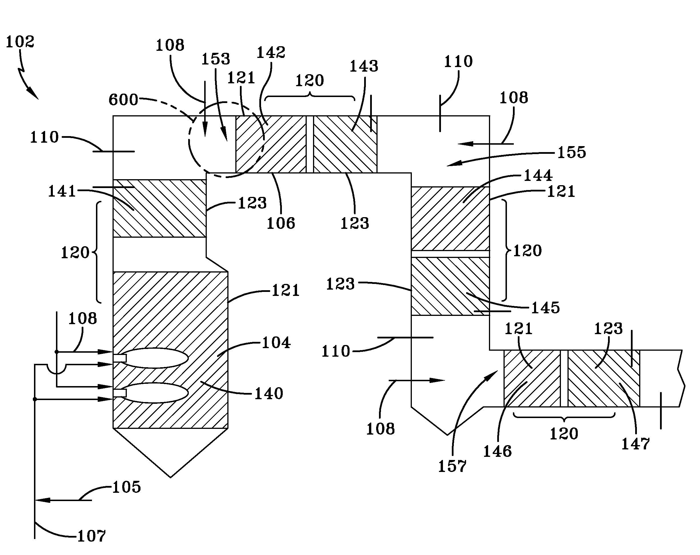
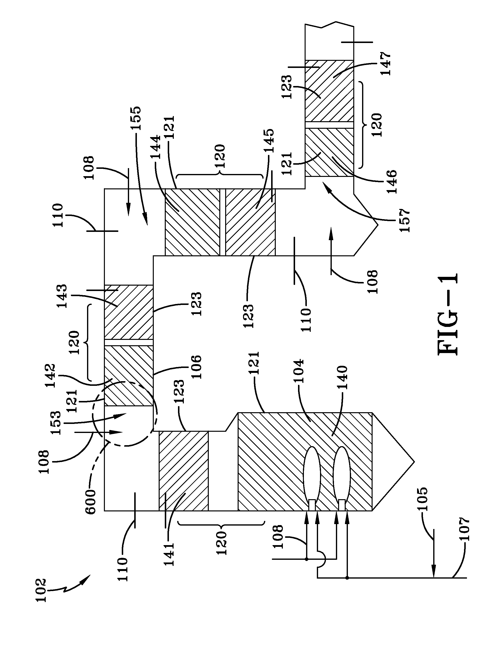
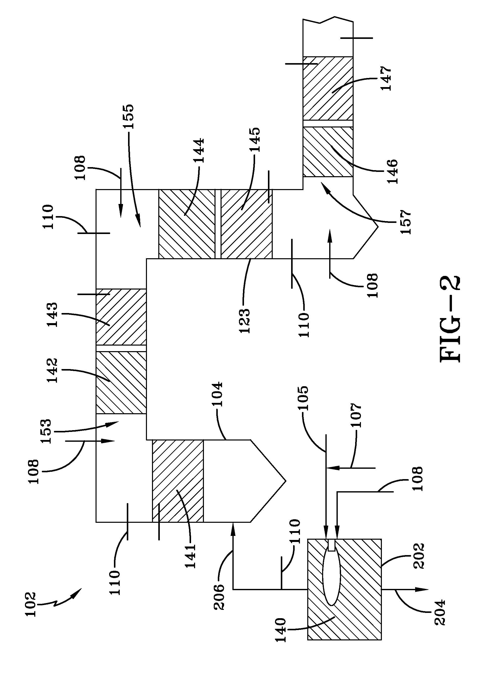
[0056]To simplify the analysis, the recycled flue gas, when utilized, is assumed to be CO2, and a single distribution of oxygen injector flow rates was employed, with the total oxygen injection rate equal to 2.4% above the stoichiometric requirement for complete combustion. Moreover, the gas temperature exiting the final heat exchange section was maintained at 796° F. (424° C.). The heat transfer taking place in heat exchangers situated between adjacent oxygen injector points was also fixed. The distributions of oxygen injector and heat transfer used in the model calculations are summarized in Tables 2 and 3, respectively.

TABLE 2InjectorO2 Injection (% of Stoichiometric Requirement)70166.470213.97036.970415.2Total102.4

TABLE 3Heat Transfer SectionsHeat Transfer Duty (MMBtu / hr)WH-140 & SH-1412150WH-142 & SH-143850WH-144 & SH-145850WH-146 & SH-147850Total4700

[0057]FIG. 10, which is representative of the above disclosed embodiments, schematically il...


PUM


Abstract

This disclosure includes a system and method of controlling fuel combustion including providing a system, measuring a property, and providing oxygen and fuel in response to the property. The system includes a furnace arranged and disposed to receive fuel and oxygen and combust the fuel and the oxygen to form a combustion fluid, a plurality of heat exchanger sections arranged and disposed to receive heat from the combustion fluid, and a plurality of oxygen injectors arranged and disposed to controllably provide oxygen to the combustion fluid to adjust composition of the combustion fluid and temperature of the combustion fluid. The property measured is selected from the group consisting of temperature of the combustion fluid, composition of the combustion fluid, temperature of the heat exchanger sections, and combinations thereof and is performed in close proximity to the oxygen injectors.

Description

CROSS-REFERENCE TO RELATED APPLICATIONS[0001]This Application is related to application Ser. No. ______, entitled “OXY / FUEL COMBUSTION SYSTEM WITH LITTLE OR NO EXCESS OXYGEN”, Attorney Docket No. 07228 USA, filed contemporaneously with this Application on Sep. 26, 2008, assigned to the assignee of the present disclosure and which is herein incorporated by reference in its entirety, application Ser. No. ______, entitled “COMBUSTION SYSTEM WITH STEAM OR WATER INJECTION”, Attorney Docket No. 07238 USA, filed contemporaneously with this Application on Sep. 26, 2008, assigned to the assignee of the present disclosure and which is herein incorporated by reference in its entirety, application Ser. No. ______, entitled “COMBUSTION SYSTEM WITH PRECOMBUSTOR”, Attorney Docket No. 07255 USA, filed contemporaneously with this Application on Sep. 26, 2008, assigned to the assignee of the present disclosure and which is herein incorporated by reference in its entirety, application Ser. No. ______,...

Claims


Application Information

Patent Timeline
Patent Type & Authority Applications(United States)
IPC IPC(8): F23N3/00F23N5/00F23B80/02F23B50/02F23J1/00
CPCF23C9/003F23C2202/20Y02E20/344F23N5/003F23N2037/28F23L7/007F23N2237/28Y02E20/34
Inventor D'AGOSTINI, MARK DANIEL
Owner AIR PROD & CHEM INC
Why Eureka
Try Eureka