Determination of leak during cpap treatment

a technology of cpap and leakage air, which is applied in the direction of fluid tightness measurement, instruments, machines/engines, etc., can solve the problems of incorrect calculation of respiratory airflow, unavoidable leakage between the mask and the subject, and only correct known methods

Active Publication Date: 2010-04-29
RESMED LTD
View PDF1 Cites 51 Cited by
  • Summary
  • Abstract
  • Description
  • Claims
  • Application Information

AI Technical Summary

Benefits of technology

[0016]This invention rapidly determines the instantaneous leak in a CPAP system without detailed modeling the source of the leak and without having to determine the precise phase in a breathing cycle at which the leak occurs. It relies instead on the use of timers to define the breathing cycle and a calculation to assu

Problems solved by technology

Leaks between the mask and the subject are unavoidable.
The known method is only correct if the pressure at the mask is constant.
If, on the other hand, the mask pressure varies with time (for example, in the case of a ventilator), assumption (i) above will be invalid, and the calculated respiratory airflow will therefore be incorrect.
In general, it ca

Method used


Image

  • Determination of leak during cpap treatment
  • Determination of leak during cpap treatment
  • Determination of leak during cpap treatment

Examples


Embodiment Construction

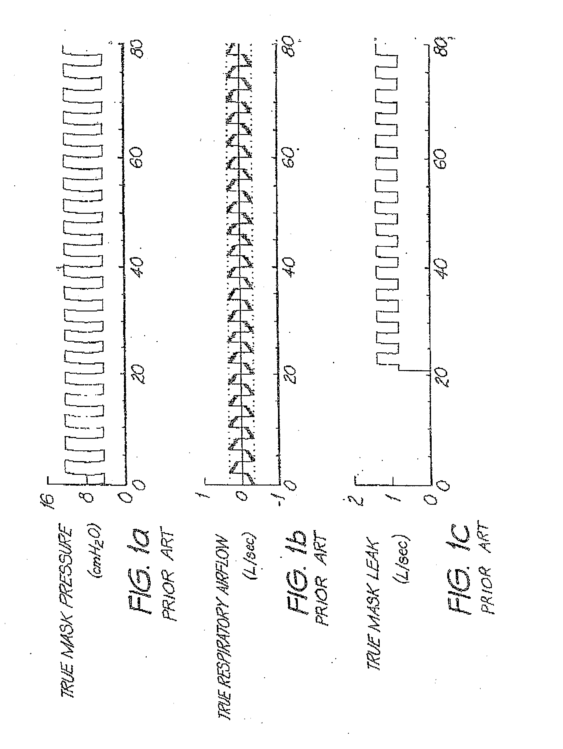
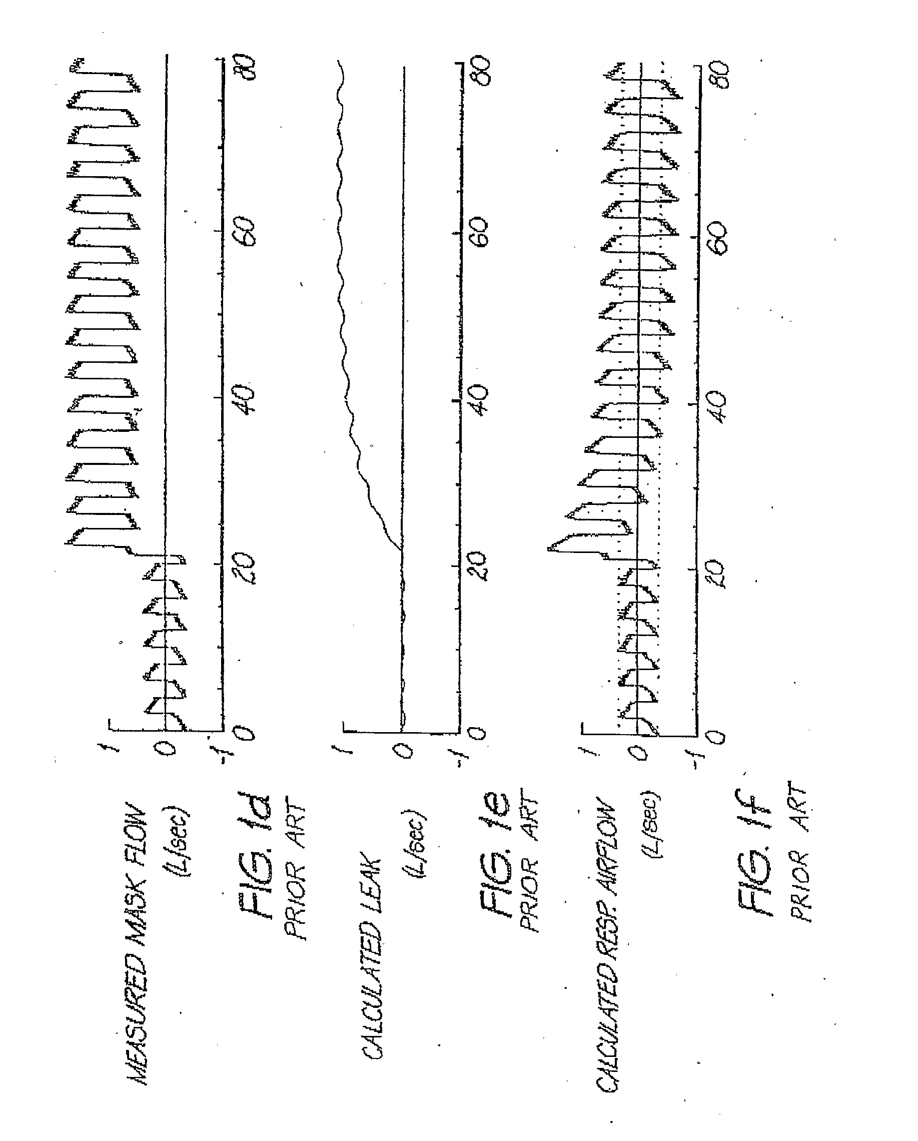
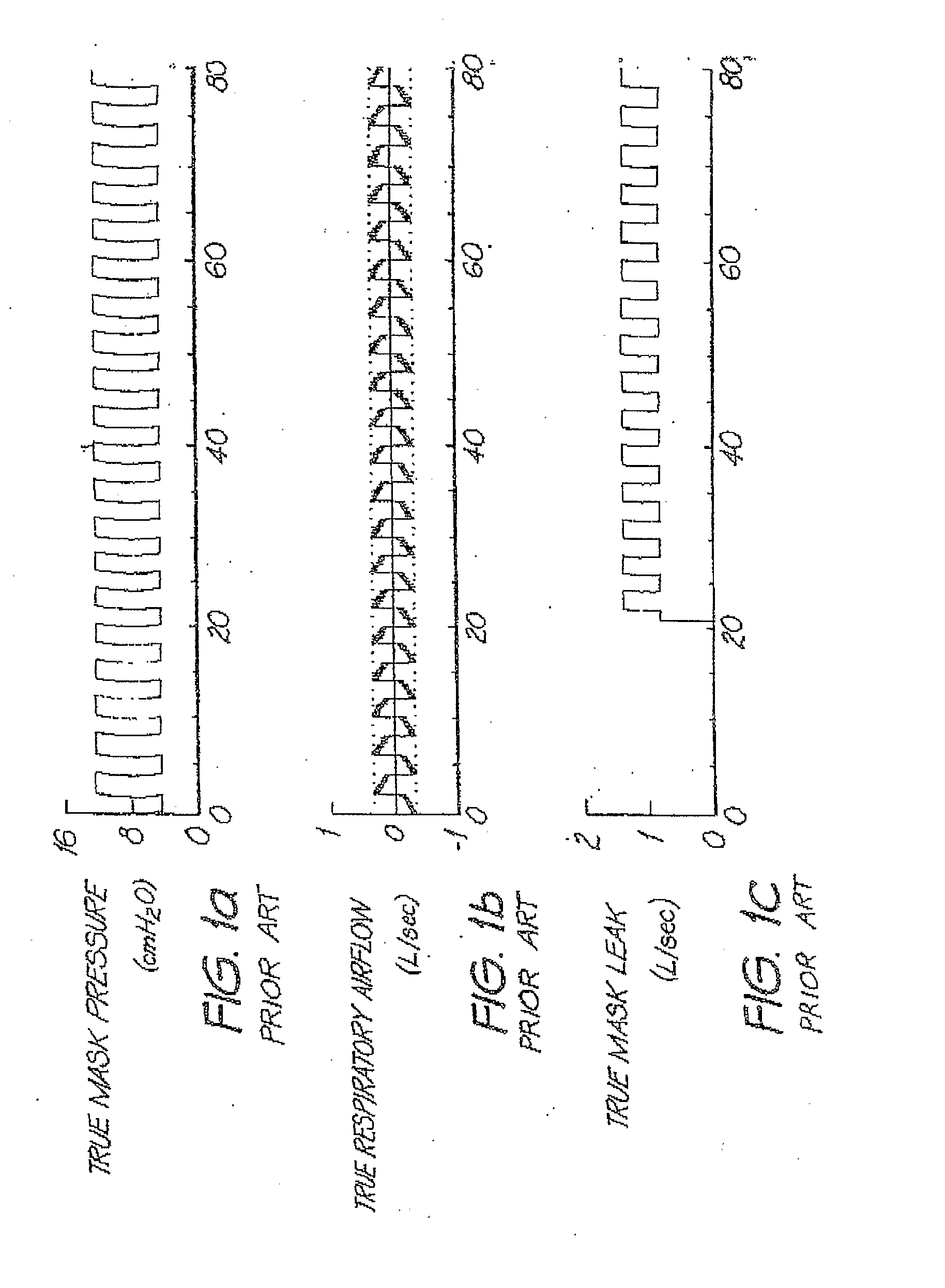
[0018]The present invention is motivated by the desire to produce a continuously updated estimate of the leak model parameter which is very stable when the actual leak parameter is stable, but which degrades progressively and gracefully to a less stable, less accurate but faster-responding estimate when the actual leak parameter is changing rapidly. The leak model parameter in question is typically an orifice constant (equivalently a leak conductance), but need not be.

[0019]A continuously updated estimate of leak conductance (in particular, continuously updated during each breath) may be calculated by performing some kind of low-pass filtering operation, such as a 1st-order low pass filter or a moving average filter, typically with a fixed window length, on the non-vent flow (equal to the sum of the respiratory flow and the instantaneous leak flow) and on the square root of the mask pressure, producing a leak conductance estimate G1, as in Berthon-Jones. This method has the advantag...


PUM


Abstract

In a CPAP or positive pressure ventilation system, leak is determined at each instant by a lookback for a time as long as single breath to establish the start of an averaging window over which low-pass filtered values used in the determination of a parameter of a leak model are averaged. A jamming index indicates whether the leak is rapidly changing. To the extent that jamming is high, the leak estimate used progressively changes from that using sliding breath-window averaging to a more robust and faster responding low-pass filter method, and adjustment of ventilatory support based on measures employing estimated respiratory flow is slowed down or stopped.

Description

FIELD OF THE INVENTION[0001]This invention relates to treatment of apneas and other respiratory disorders. In particular it relates to methods and apparatus for the determination of leakage airflow and true respiratory airflow, during the mechanical application of positive airway pressure.BACKGROUND OF THE INVENTION[0002]For the treatment of apneas and other respiratory disorders, breathable gas is supplied from a mechanical respirator or ventilator, for example via a mask, at a pressure which may be higher during inspiration and lower during expiration. (In this specification any reference to a “mask” is to be understood as including all forms of devices for passing breathable gas to a person's airway, including nose masks, nose and mouth masks, nasal prongs / pillows and endrotracheal or tracheostomy tubes. The term “ventilator” is used to describe any device that does part of the work of breathing.) Typically one measures the subject's respiratory airflow during mechanical ventilat...

Claims


Application Information

Patent Timeline
IPC IPC(8): A61M16/00G01M3/02G06F19/00
CPCA61M16/0051A61M2016/0021A61M2016/0036A61M16/0057A61M16/06A61M2205/15A61M2205/16A61M16/024A61M2205/50
Inventor BASSIN, DAVID JOHN
Owner RESMED LTD
Why Eureka
Try Eureka