Driving apparatus

a technology of driving apparatus and motor, which is applied in the direction of generator/motor, nanoinformatics, instruments, etc., can solve the problems of unstable stage operation, difficult control of position, and large gain of oscillation (i.e. oscillation range), so as to increase the recording capacity of the recording medium, reduce power consumption, and small size

Inactive Publication Date: 2010-04-29
PIONEER CORP
View PDF8 Cites 7 Cited by
  • Summary
  • Abstract
  • Description
  • Claims
  • Application Information

AI Technical Summary

Benefits of technology

[0004]On the other hand, for the MEMS actuator, due to its small size, lower power consumption is desired. Moreover, in order to increase a recording capacity of the recording medium, it is aimed to increase its recording density to be extremely high and to reduce a recording pitch to be on the order of nanometers. When the data is recorded into such an ultramicro area by using the probes, performances are influenced by slight distortion in the driving position of the stage and position repeatability. Thus, it is desired to displace the stage more efficiently.

Problems solved by technology

As described above, the reason why a force is applied to the stage to oscillate the stage at a lower frequency than the minimum resonance frequency is because it is considered that if the force is applied to the stage to oscillate the stage at a frequency near a resonance frequency, the gain of the oscillation (i.e. oscillation range) becomes too large, or it becomes harder to control a position at a frequency higher than the resonance frequency, resulting in unstable operations of the stage (i.e. operations of the MEMS actuator).

Method used


Image

  • Driving apparatus
  • Driving apparatus
  • Driving apparatus

Examples


examples

[0076]Hereinafter, examples of the driving apparatus of the present invention will be described with reference to the drawings.

(1) Information Recording / Reproducing Apparatus

[0077]Firstly, with reference to FIG. 1 to FIG. 4, an explanation will be given on an information recording / reproducing apparatus provided with any of the examples of the driving apparatus of the present invention. Incidentally, here, an explanation will be given on a ferroelectric recording / reproducing apparatus which performs a recording operation or reproduction operation on a recording medium 30 in which a ferroelectric substance is used as a recording material.

(1-1) Structure

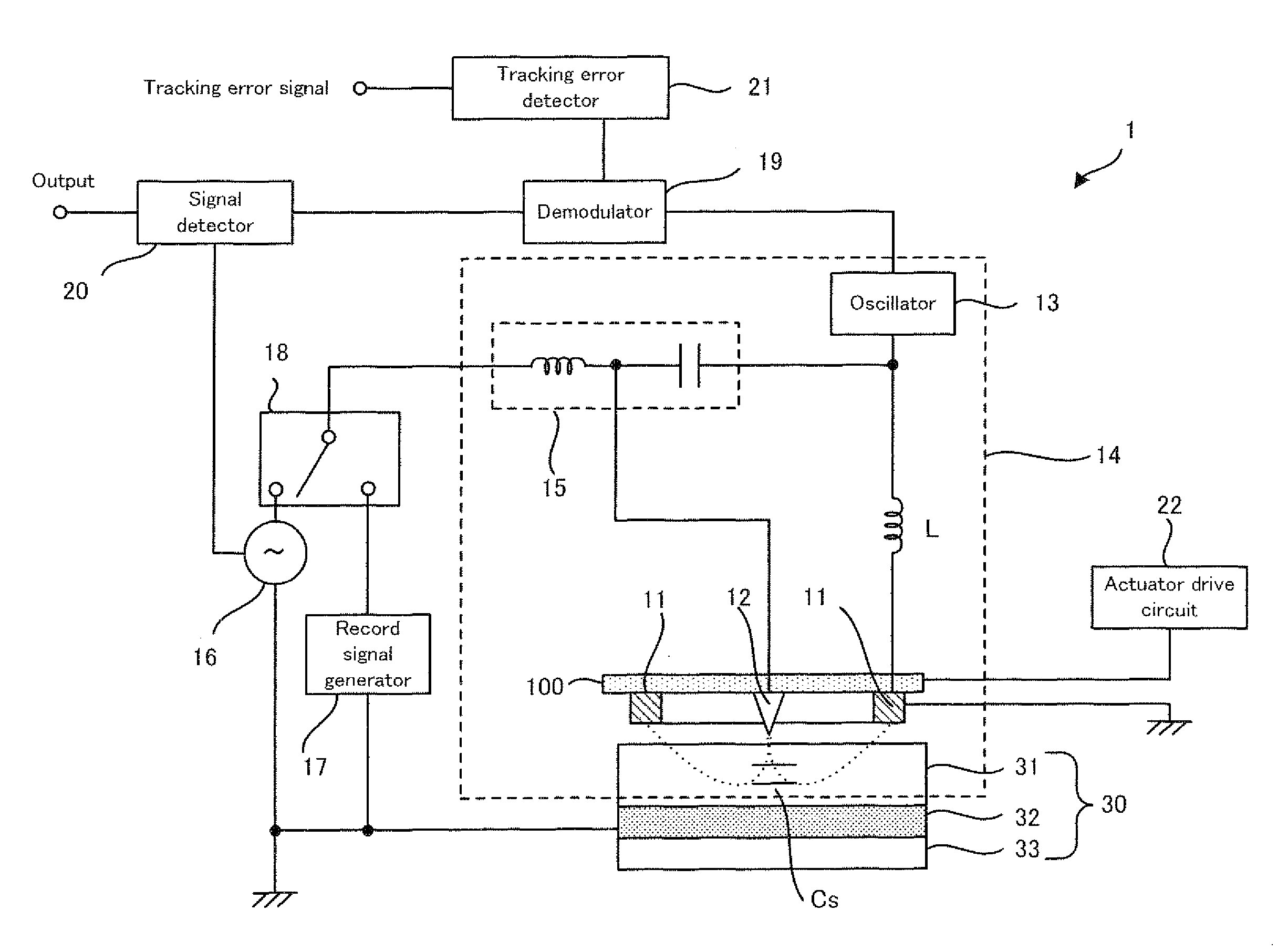
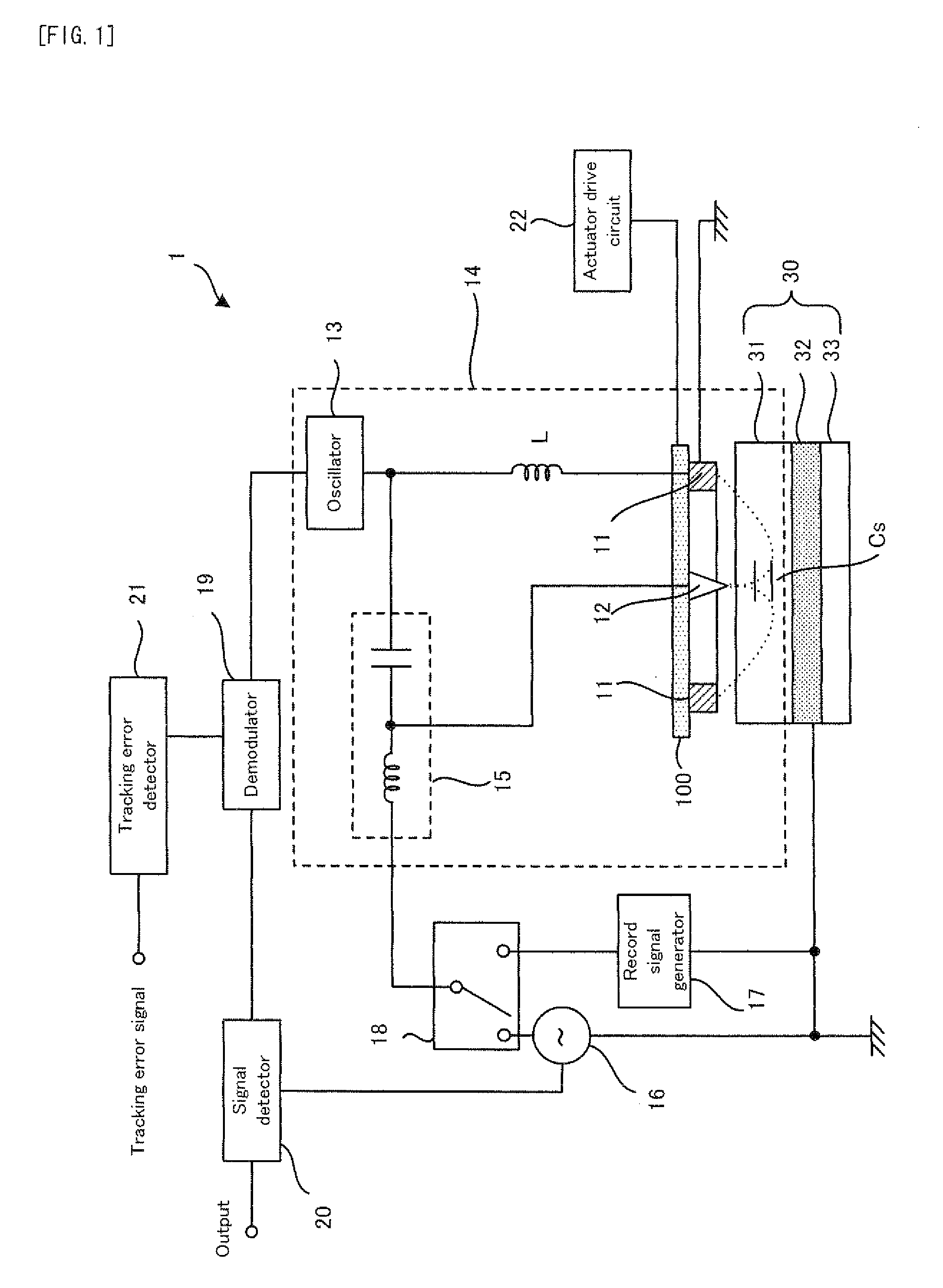
[0078]Firstly, the structure of a ferroelectric recording / reproducing apparatus in the example will be explained with reference to FIG. 1. FIG. 1 is a block diagram conceptually showing the structure of a ferroelectric recording / reproducing apparatus in example.

[0079]As shown in FIG. 1, a ferroelectric recording / reproducing apparatus 1 ...

third example

(2-1-3) Third Example

[0152]Next, with reference to FIG. 12, a driving apparatus 100g in a third example will be explained. FIG. 12 is a plan view conceptually showing the structure of the driving apparatus 100g in the third example. Incidentally, the same constituents as those of the driving apparatus 100a in the first example described above (and moreover, the driving apparatus 100b and the driving apparatus 100c) and the driving apparatus 100d in the second example (and moreover, the driving apparatus 100e and the driving apparatus 100f) will carry the same referential numerals, and the detailed explanation thereof will be omitted.

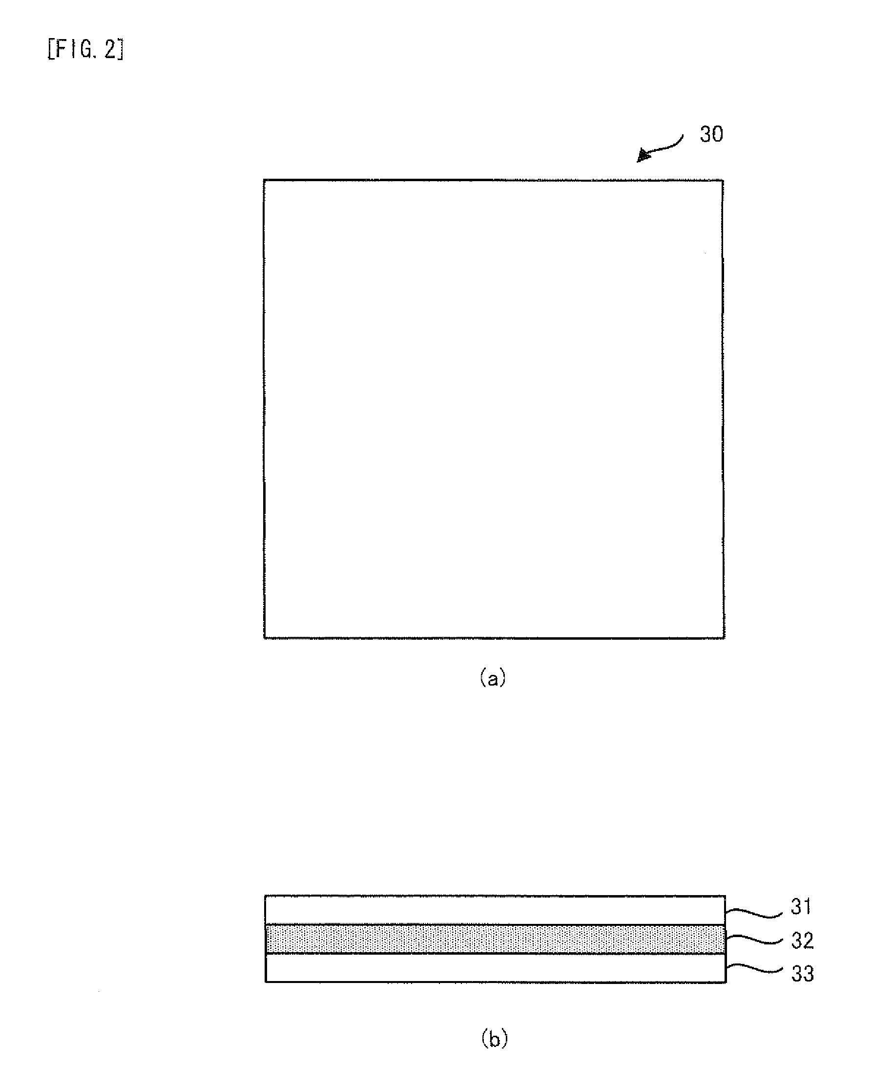
[0153]As shown in FIG. 12, the driving apparatus 100d in the third example is provided with the base 110, the two suspensions 120, the stage 130, and the two pairs of electrodes 141, piezoelectric elements 142, electrodes 143, and force transmission mechanisms 144, as in the driving apparatus 100d in the second example.

[0154]In the driving apparatus 100g...

fourth example

(2-1-4) Fourth Example

[0160]Next, with reference to FIG. 15 and FIG. 16, a driving apparatus 100j in a fourth example will be explained. FIG. 15 is a plan view conceptually showing the structure of the driving apparatus 100j in the fourth example. FIG. 16 is a plan view conceptually showing an aspect when the driving apparatus 100j in the fourth example operates. Incidentally, the same constituents as those of the driving apparatus 100a in the first example described above (and moreover, the driving apparatus 100b and the driving apparatus 100c), the driving apparatus 100d in the second example (and moreover, the driving apparatus 100e and the driving apparatus 100o, and the driving apparatus 100g in the third example (and moreover, the driving apparatus 100h and the driving apparatus 100i) will carry the same referential numerals, and the detailed explanation thereof will be omitted.

[0161]As shown in FIG. 15, the driving apparatus 100j in the fourth example is provided with the bas...


PUM


Abstract

A driving apparatus (100q) is provided with: a first base portion (110-1); a first stage portion (130-1); a first elastic portion (120-1) which has elasticity to displace the first stage portion in one direction (Y axis); a second stage portion (130-2) which is disposed on the first stage portion and on which a driven object (12) is mounted; a second elastic portion (120-2) which has elasticity to displace the second stage in other direction (X axis); a first applying device (151-1, 152-1, 22) for applying an excitation force for displacing the first stage portion such that the first stage portion is resonated in the one direction at a resonance frequency determined by the first stage portion and the first elastic portion; and a second applying device (151-2, 152-2, 22) for applying a driving force for displacing, in a stepwise manner or in a continuous manner, the second stage portion in the other direction.

Description

TECHNICAL FIELD[0001]The present invention relates to a driving apparatus for driving a probe or the like in a uniaxial direction or biaxial directions so that the probe scans the surface or the like of a medium.BACKGROUND ART[0002]For example, the development of a probe memory has been advanced which records data onto a recording medium or which reproduces the data recorded on the recording medium by displacing a probe array including a plurality of probes along a recording surface of the recording medium. In such a probe memory, the location of the probe array with respect to the recording medium (in other words, a position relation between the probe array and the recording medium) is determined, for example, by displacing a stage provided with the probe array. In other words, the location of the probe array with respect to the recording medium is determined by the operations of a MEMS (Micro Electro Mechanical System) actuator which is provided with the stage and which can displa...

Claims


Application Information

Patent Timeline
Patent Type & Authority Applications(United States)
IPC IPC(8): H02N2/04H02K41/02
CPCB82Y10/00G11B9/1436G11B9/02
Inventor SUZUKI, JUN
Owner PIONEER CORP
Why Eureka
Try Eureka