Channel letter lighting system using high output white light emitting diodes

a light-emitting diode, high-output technology, applied in lighting support devices, lighting and heating apparatus, instruments, etc., can solve the problems of bulb failure, consuming a relatively large amount of power, and relatively short life (20,000 hours), and achieve the effect of increasing the length of the conductor

Inactive Publication Date: 2010-06-17
THE SLOAN COMPANY INC DBA SLOANLED
View PDF13 Cites 20 Cited by
  • Summary
  • Abstract
  • Description
  • Claims
  • Application Information

AI Technical Summary

Benefits of technology

[0015]Another embodiment of a lighting system according to the present invention comprises a plurality of lighting units connected to and interconnected by a conductor. Each of the lighting units comprises a housing and a printed circuit board (PCB) mounted to the housing. The PCT has having a plurality of light emitting elements arranged so that an electrical signal applied to conductor causes the light emitting elements to emit light substantially away from the housing. A plurality of additional conductor sections is included, each of which is associated with a respective one of the lighting units to increase the length of the conductor between adjacent ones of the lighting units.

Problems solved by technology

These light sources, however, have a relatively short life (20,000 hours), are fragile, operate at high voltage (7,000 to 15,000 volts for neon) and can consume a relatively large amount of power.
Neon bulbs can also experience difficulty with cold starting, which can lead to the bulb's failure.
These chains are typically sold at a cost per measure of length, and the cost per length is typically greater for lighting systems having higher density.
Conventional lighting units, however, offer little flexibility in reducing the number of LEDs in certain ones or all of the LED units in a chain.

Method used


Image

  • Channel letter lighting system using high output white light emitting diodes
  • Channel letter lighting system using high output white light emitting diodes
  • Channel letter lighting system using high output white light emitting diodes

Examples


Embodiment Construction

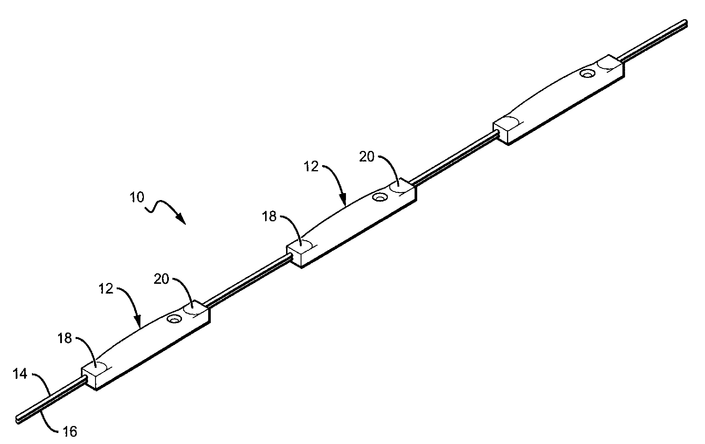
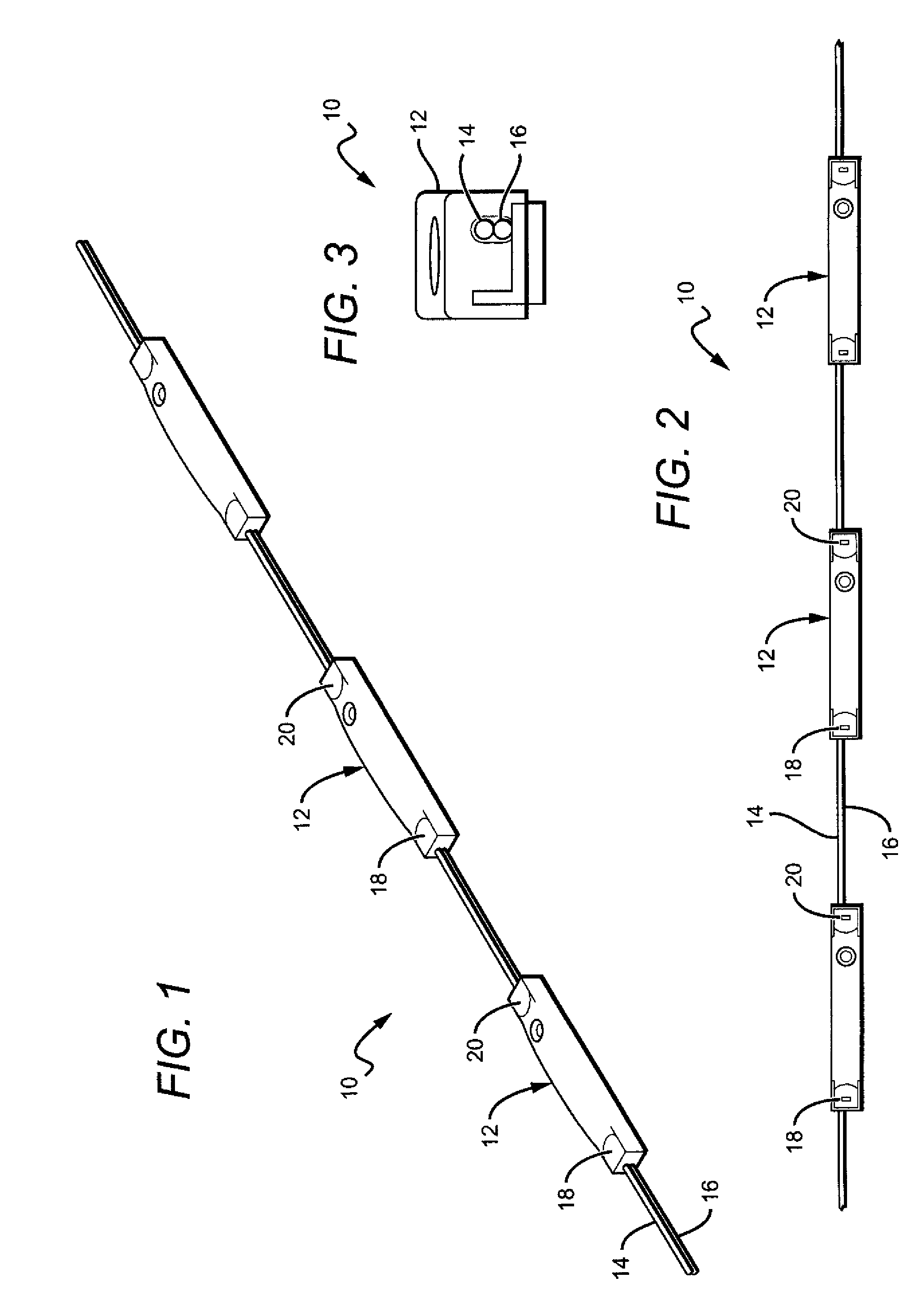
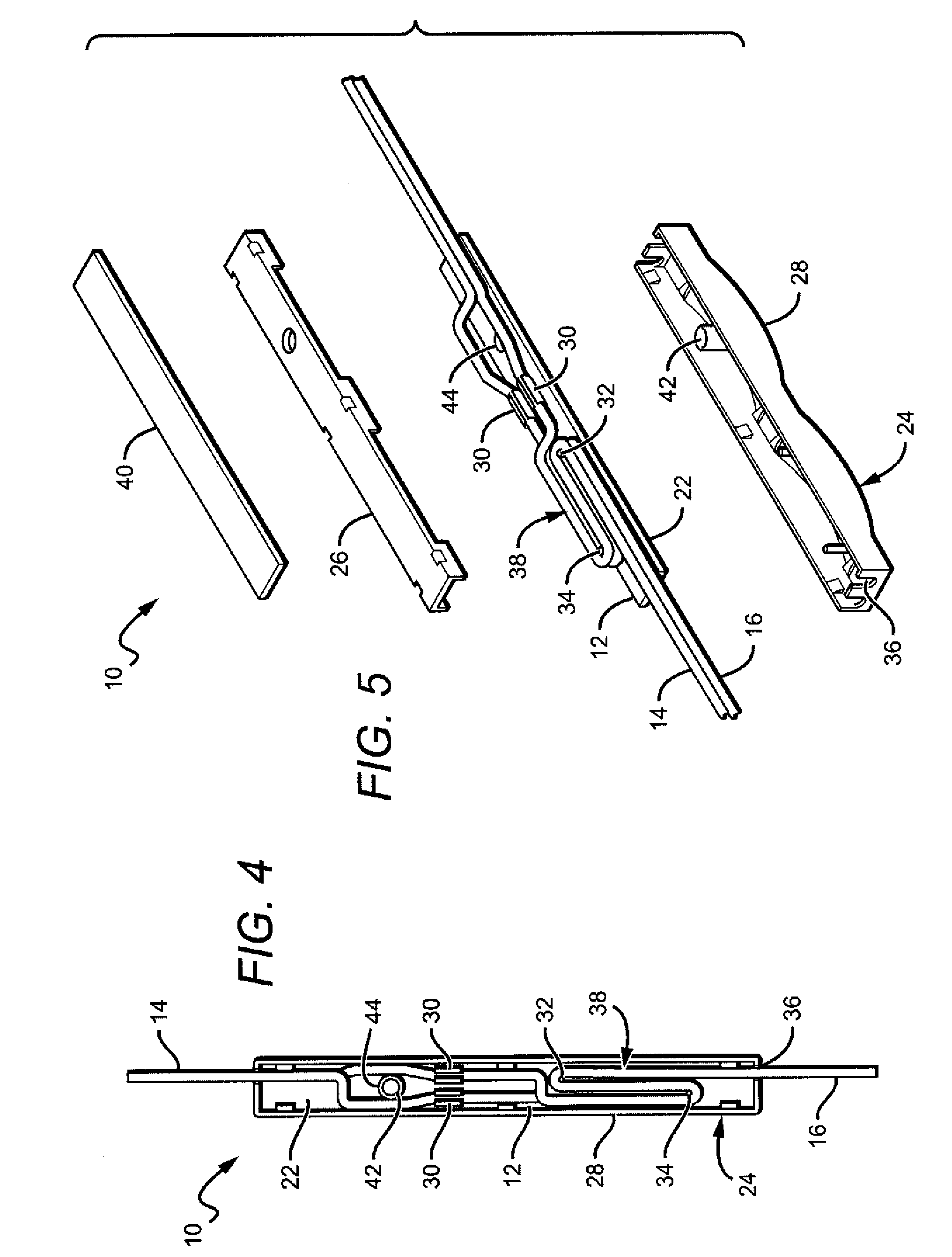
[0035]The present invention provides a lighting system that can be used in many different applications such as structural lighting, display lighting and ingress / egress lighting, but is particularly applicable to channel letter lighting. The systems according to the present invention provide lighting units that are interconnected in a chain by electrical conductors so that an electrical signal applied to the input end of the conductors spreads to the lighting units, causing them to emit light. According to the present invention, the conductors between the LED units can have an adjustable length to allow for the length of conductors to be altered in the, which allows for the density of the LED units to be customized to meet the particular application. For example, in channel letter applications there may be instances where chains or sections of chains having different densities are desired, and the present invention allows for the density to be altered in the field to meet these diffe...


PUM


Abstract

A channel letter lighting system comprising a plurality of lighting units that are interconnected by a conductor. Each of the units is coupled to the conductor such that an electrical signal applied to the conductor causes the lighting units to emit light. The length of the conductor between said units is adjustable to vary the distance between adjacent ones of the lighting units. In other embodiment the lighting units comprise a plurality of emitters. A conductor is included for carrying an electrical signal with the lighting units connected to and interconnected by a conductor. An electrical signal applied to the conductor causes the emitters emit light. The lighting units are separable into sections each of which comprise at least one of the plurality of emitters and each of which remains connected to the conductor. The length of the conductor between the sections can be adjustable to vary the distance between adjacent ones of the sections.

Description

BACKGROUND OF THE INVENTION[0001]1. Field of the Invention[0002]This invention relates to lighting units using light emitting diodes (LEDs), and more particularly to LED based interconnected lighting units for different illumination applications such as illuminating channel letters.[0003]2. Description of the Related Art[0004]Recent developments in LEDs have resulted in devices that are brighter, more efficient and more reliable. LEDs are rugged, consume less power, have a relatively long life (up to 100,000 hours), operate at low voltage, and are 30 to 70% more energy efficient than conventional lights, such as incandescent, neon or fluorescent bulbs. As a result of these developments, LEDs are becoming utilized in many more lighting applications that were previously the realm of incandescent, neon or fluorescent light sources.[0005]Channel letters are commonly found on the outside of buildings and are often used to advertise the name of the business. They are typically constructed...

Claims


Application Information

Patent Timeline
Patent Type & Authority Applications(United States)
IPC IPC(8): F21V21/00F21S4/00
CPCF21Y2101/02G09F13/0404F21S4/001H05K3/0052G09F13/22F21V23/001F21S4/10F21Y2115/10
Inventor SLOAN, THOMAS C.QUAAL, BRUCE
Owner THE SLOAN COMPANY INC DBA SLOANLED
Why Eureka
Try Eureka