LED lens

a technology of led lenses and lenses, applied in the field of lenses, can solve problems such as light-emitting bright spots, and achieve the effect of reducing the appearance of bright spots

Active Publication Date: 2010-07-15
ILUMISYS
View PDF101 Cites 124 Cited by
  • Summary
  • Abstract
  • Description
  • Claims
  • Application Information

AI Technical Summary

Benefits of technology

[0005]A light modifier for an LED which produces light about a central axis is described herein. The light modifier can reduce the appearance of bright spots resulting from the directional light output of the LED. In one example of such a light modifier, a lens defines an indentation. The indentation is angled relative to the central axis by an amount less than a complementary angle of a critical angle of the lens along the indentation.

Problems solved by technology

Known LEDs provide directional light output that may result in the appearance of bright spots of light.

Method used


Image

  • LED lens
  • LED lens
  • LED lens

Examples


Embodiment Construction

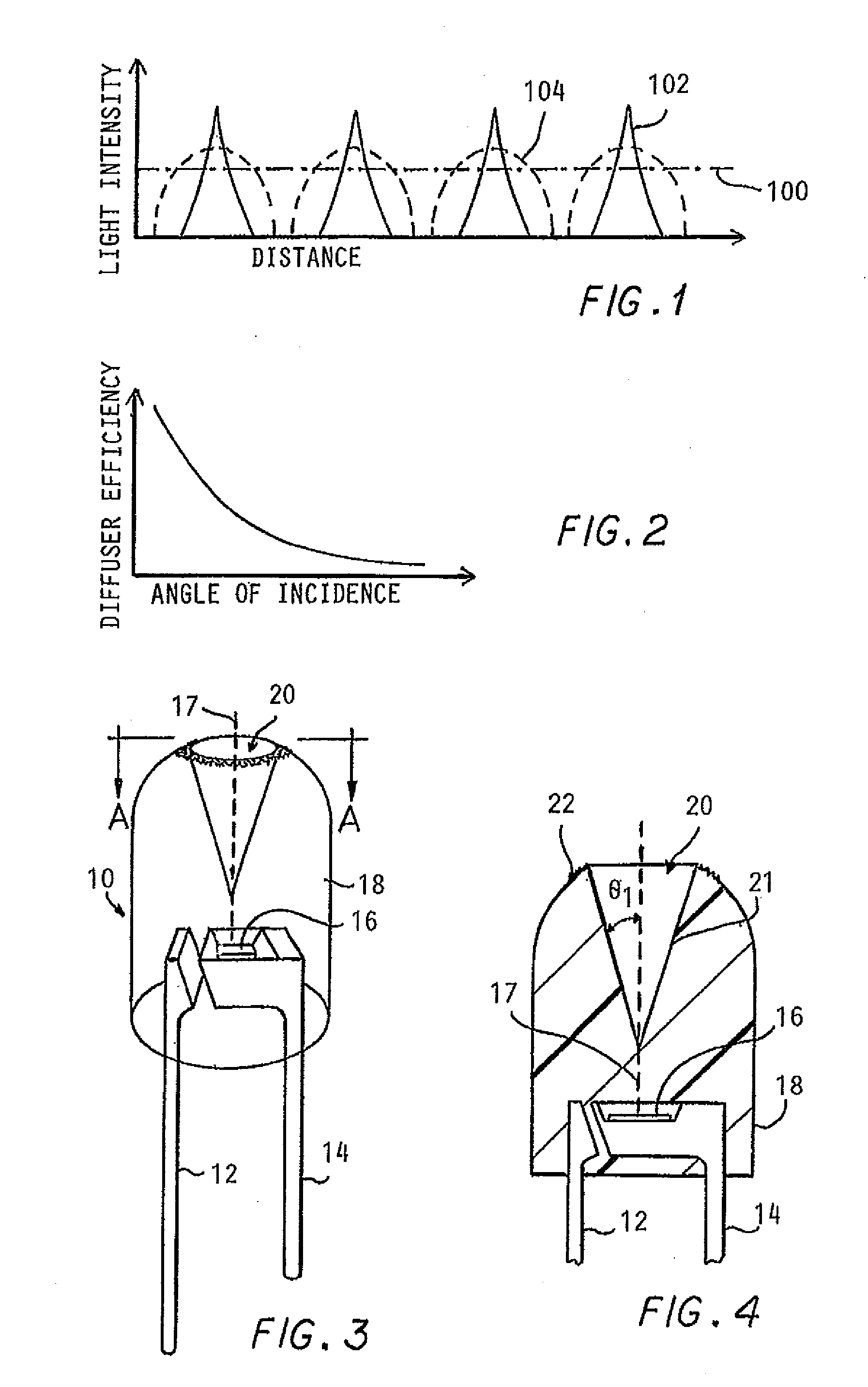
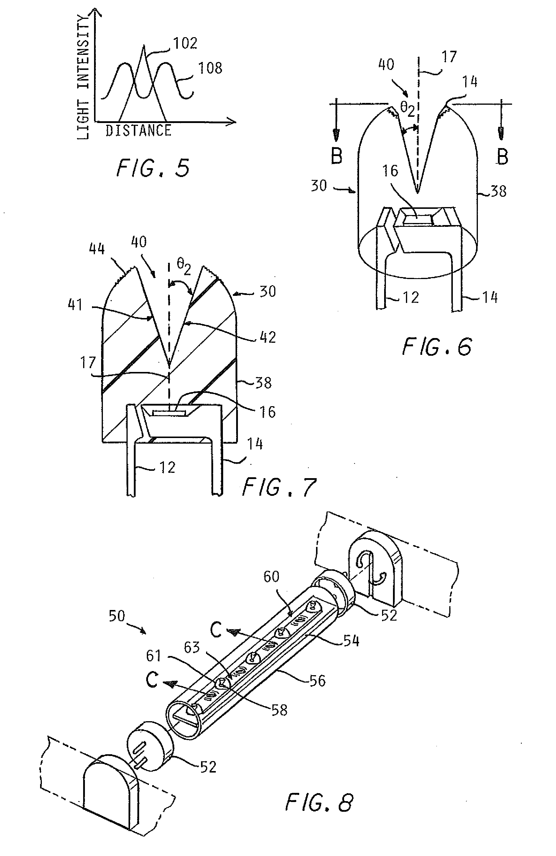
[0040]Examples of lenses for use with LEDs are discussed below with reference to FIGS. 1-14. As shown in FIG. 1, a fluorescent tube produces a generally constant light intensity along its entire length, which is indicated by line 100. An LED, however, generally produces light in a Lambertian distribution, with a majority of the light within a few degrees of a central axis normal to the LED. The light concentrated around the central axis is referred to as a “bright spot,” When LEDs are used in a fluorescent tube shaped light, the light can have the appearance of several bright spots. For example, line 102 in FIG. 1 includes four spikes, each of which represents the bright spot of light produced by an LED or a closely-spaced group of LEDs (e.g., a six-pack package of LEDs). A similar light distribution problem can exist when LEDs are used in other types of lights, such as LED-based flashlights and LED-based lights sized to replace incandescent bulbs.

[0041]A diffuser can be placed in t...


PUM

PropertyMeasurementUnit
power ratingaaaaaaaaaa

Abstract

A light modifier for an LED producing light about a central axis is provided. The light modifier includes a lens defining an indentation. The indentation is angled relative to the central axis by an amount less than a complementary angle of a critical angle of the lens along the indentation. The lens can reduce the appearance of a bright spot created by the LED.

Description

CROSS-REFERENCE TO RELATED APPLICATION[0001]This application claims priority from U.S. Provisional Patent Application No. 61 / 144,853, filed Jan. 15, 2009, the entire contents of which is incorporated herein by reference.TECHNICAL FIELD[0002]The present invention relates to a lens for an LED.BACKGROUND[0003]Light emitting diodes (LEDs) have many advantages over fluorescent tubes. LEDs are more efficient, last longer, and are less sensitive to vibrations and low temperatures. To take advantage of the benefits of LEDs, LEDs are being included in lights of various shapes, such as in the shape of fluorescent tubes. However, known LEDs are constrained by the directional light output of the LEDs in contrast to, for example, the uniform non-directional light output of fluorescent tubes. One way of spreading the directional light output from an LED is to direct the light through a diffuser.BRIEF SUMMARY[0004]Known LEDs provide directional light output that may result in the appearance of bri...

Claims


Application Information

Patent Timeline
Patent Type & Authority Applications(United States)
IPC IPC(8): H01L33/00F21V5/00G02B6/00B29D11/00
CPCB29D11/00278F21K9/17F21Y2101/02F21V5/048H01L33/54F21K9/10F21Y2103/00H01L2924/181H01L2924/1815F21Y2115/10F21V7/0083F21V7/0091F21V7/041F21Y2103/10F21K9/68F21K9/69H01L2924/00012F21K9/27
Inventor SIMON, DAVID L.IVEY, JOHNLAVERING, GORDON R.
Owner ILUMISYS
Why Eureka
Try Eureka