

Information terminal device
- Summary
- Abstract
- Description
- Claims
- Application Information
AI Technical Summary
Benefits of technology
Problems solved by technology
Method used
Image

Examples
Embodiment Construction
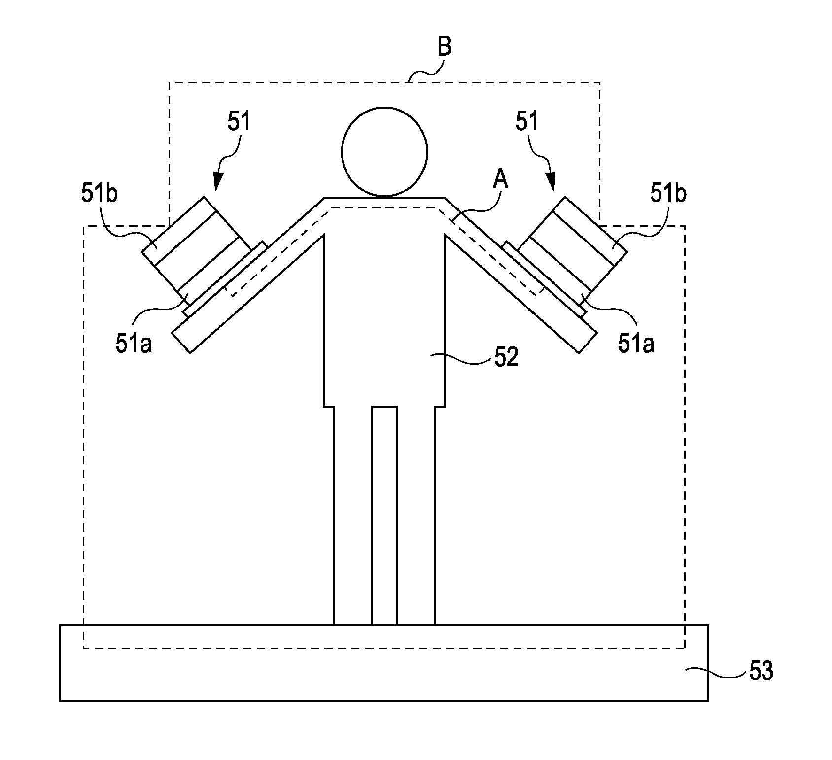
[0021]The human body communication using the electric field requires a forward path (path A shown in FIG. 5) through which the signal flows via the capacitance coupling among the transmitter, the human body, and the receiver, and a return path (path B shown in FIG. 5) through which the signal flows via the capacitance coupling between the receiver and derivative such as air, or between the conductor such as earth and the receiver. Preferably, the human side electrode 51a (transmitter and receiver sides) for constituting the forward path intensifies the capacitance coupling with respect to the human body 52, and the capacitance coupling with the human side electrode 51a (transmitter and receiver sides) via the human body 52. Preferably, the capacitance coupling between the external electrode 51b (transmitter and receiver sides) for constituting the forward path is reduced, and the capacitance coupling with the external electrode 51b (transmitter and receiver sides) is intensified. Th...
PUM
 Abstract
Description
Claims
Application Information