

Method for operating marine seismic vibrator array to enhance low frequency output
a technology of low frequency output and vibrator array, which is applied in the field of marine seismic vibrators, can solve the problems of difficult control of such motion so as to faithfully correspond to the electrical control signal
- Summary
- Abstract
- Description
- Claims
- Application Information
AI Technical Summary
Problems solved by technology
Method used
Image

Examples
Embodiment Construction
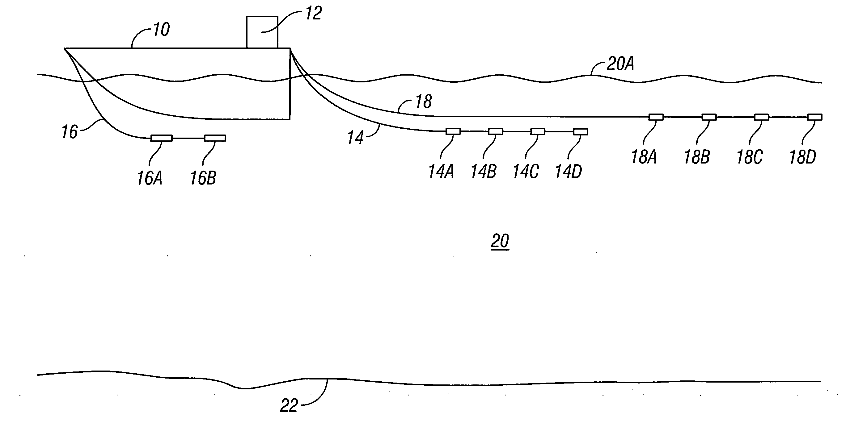
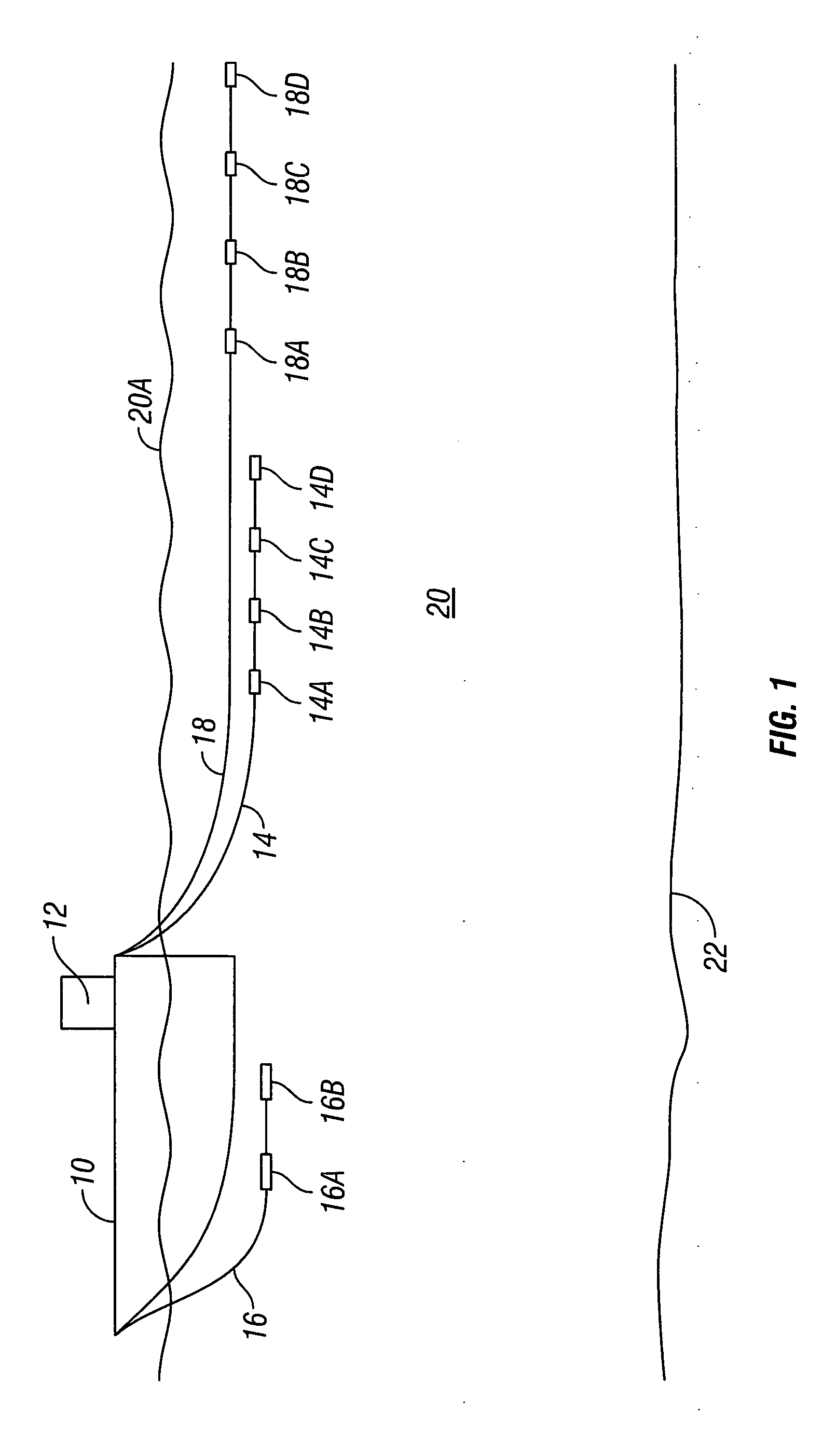
[0014]An acoustic source emitting frequency f1 will also emit harmonic frequencies 2f1, 3f1 . . . because of non-linear behavior of the components of the acoustic source. Two acoustic sources spatially close to each other, and emitting energy at frequencies f1 and f2, respectively, will also result in frequencies f1+f2 and |f1−f2|. It is the latter frequency, called a “sub-harmonic” that is of interest in the present invention. Assuming, for example, frequencies of 10 and 12 Hz for the foregoing two sources, the combination of the two sources will result in 2 Hz sub-harmonic energy being propagated through the medium to which the sources are coupled. Such an arrangement is called a parametric array.
[0015]The theory of parametric arrays states two important points. First, the amplitude of the sub-harmonic |f1−f2| attenuates 12 dB / octave compared to the amplitude of the fundamental frequencies. Second, the footprint (Fresnel zone) of the sub-harmonic is substantially the same as that ...
PUM
 Abstract
Description
Claims
Application Information