Welding booth

a booth and air cleaning technology, applied in ventilation systems, heating types, stoves or ranges, etc., can solve the problems of waste of valuable floor space, inability to clean up after welding, so as to reduce the effect of spa

Active Publication Date: 2010-10-14
AVANI ENVIRONMENTAL INTL INC
View PDF6 Cites 4 Cited by
  • Summary
  • Abstract
  • Description
  • Claims
  • Application Information

AI Technical Summary

Benefits of technology

[0011]The present invention relates to a new type of welding chamber that, while it can stand alone, allows for a reduced space when multiple chambers are used. The particular configuration is designed such that either side-to-side, back-to-back, or both configurations can be achieved with multiple booths of the present invention.

Problems solved by technology

The welding of metal parts and welding to build products is an inherently dangerous endeavor.
Not only are the sparks and hot metal pieces easy to start fires, cause burns, and the like, but the gases and dust created during the welding process can be toxic, as well as detrimental, to the product being produced.
Not only does this older system waste valuable floor space, but it adds considerably to the maintenance and cleaning of a welding system.
These work well, but expose the worker who cleans the unit to the filter and interior of the filter chamber every time the tray needs to be cleaned, exposing the worker and surrounding environment to a higher level of contaminants.
The system describes methods for preventing the recontamination of the air filter after it has been pulsed but, nothing to prevent exposure to the filter every time the collection tray is cleaned.
Upright posts and cross beams are a fairly standard construction method for framing systems in general, and as with any older technology, present a variety of problems including their size and greater weight.
These booths all tend to take up much room on the floor, and are not very cost effective for smaller welding jobs.

Method used


Image

  • Welding booth
  • Welding booth
  • Welding booth

Examples


Embodiment Construction

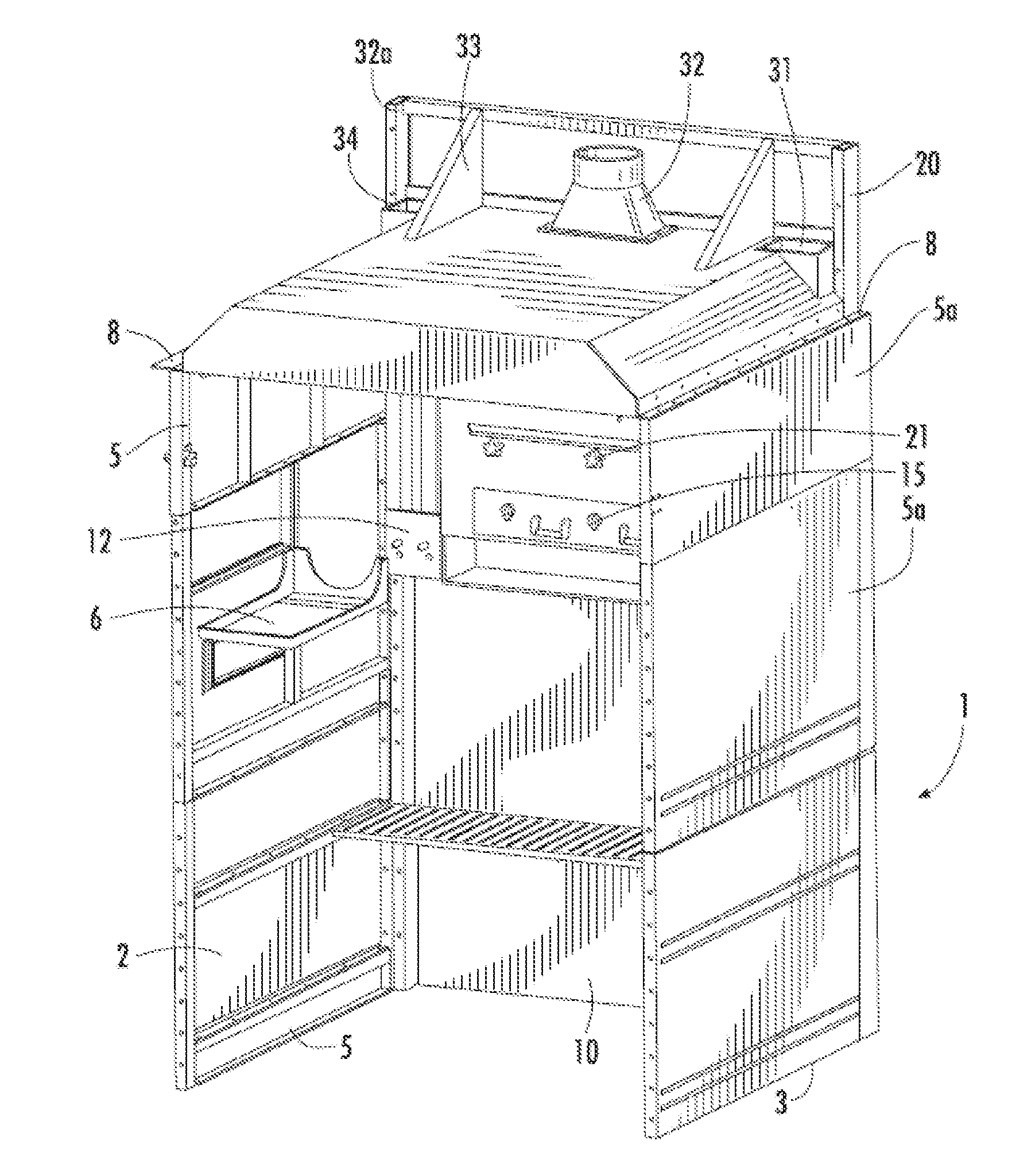
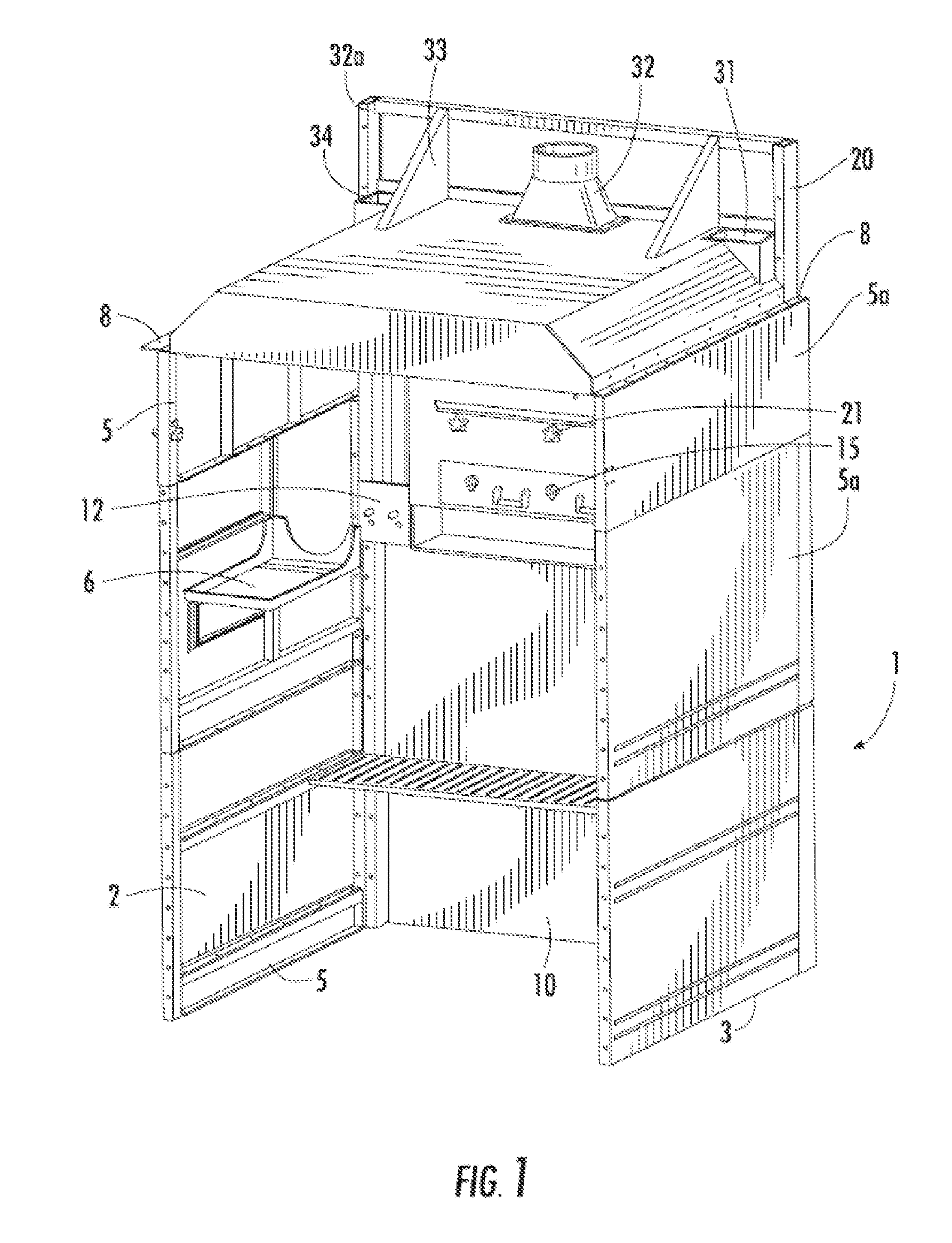
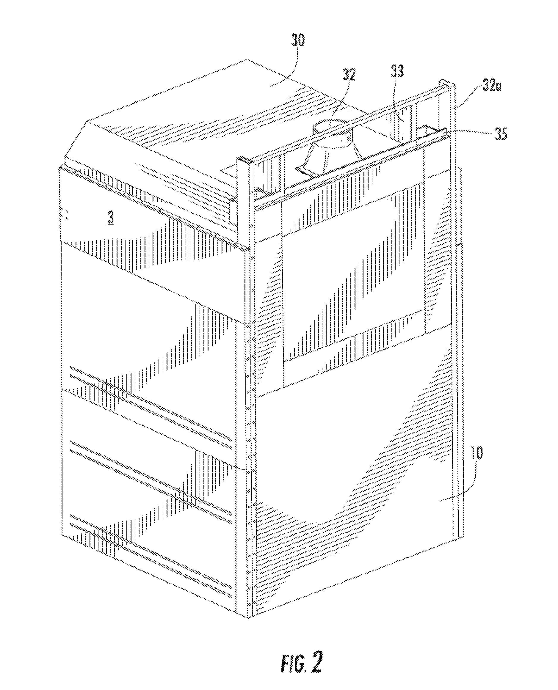
[0023]While this invention is susceptible to embodiment in many different forms, there is shown in the drawings, and will herein be described in detail specific embodiments, with the understanding that the present disclosure of such embodiments is to be considered as an example of the principles, and not intended to limit the invention to the specific embodiments shown and described. In the description below, like reference numerals are used to describe the same, similar, or corresponding parts in the several views of the drawings. This detailed description defines the meaning of the terms used herein, and specifically describes embodiments, in order for those skilled in the art to practice the invention.

[0024]The terms “a” or “an”, as used herein, are defined as one or as more than one. The term “plurality”, as used herein, is defined as two or as more than two. The term “another”, as used herein, is defined as at least a second or more. The terms “including” and / or “having”, as us...


PUM

PropertyMeasurementUnit
diameteraaaaaaaaaa
sizeaaaaaaaaaa
weightaaaaaaaaaa

Abstract

The present invention relates to a welding booth that has a small foot print and can be joined to other booths for maximization of floor space use.

Description

COPYRIGHT NOTICE[0001]A portion of the disclosure of this patent contains material that is subject to copyright protection. The copyright owner has no objection to the reproduction by anyone of the patent document or the patent disclosure as it appears in the Patent and Trademark Office patent files or records, but otherwise reserves all copyright rights whatsoever.BACKGROUND OF THE INVENTION[0002]1. Field of the Invention[0003]The present invention relates to air cleaning systems for welding chambers. In particular, the present invention relates to an air cleaning system booth, a small footprint and the ability to have many units in a confined area without substantial air handling problems.[0004]2. Description of Related Art[0005]The welding of metal parts and welding to build products is an inherently dangerous endeavor. Not only are the sparks and hot metal pieces easy to start fires, cause burns, and the like, but the gases and dust created during the welding process can be toxi...

Claims


Application Information

Patent Timeline
Patent Type & Authority Applications(United States)
IPC IPC(8): B23K9/00
CPCB23K9/324
Inventor SITHES, EDWIN F.
Owner AVANI ENVIRONMENTAL INTL INC
Why Eureka
Try Eureka