Tool organizing device

a tool and tool technology, applied in the field of tool organizing devices, can solve the problems of not being able to suitably organize the tool members or objects, the required tool members or objects may not be easily obtained by users, etc., and achieve the effect of convenient and quick acquisition by users

Inactive Publication Date: 2010-11-25
CHENG YING CHOU
View PDF15 Cites 17 Cited by
  • Summary
  • Abstract
  • Description
  • Claims
  • Application Information

AI Technical Summary

Benefits of technology

[0010]The primary objective of the present invention is to provide a tool organizing device including an adjustable structure for suitably storing and displaying or supporting various tool members and for allowing the tool members to be easily and quickly obtained by the users.

Problems solved by technology

However, the shelves may only be provided in the typical utility carts and used to randomly support the various tool members or objects, but may not be used to suitably organize the tool members or objects.
However, the shelves or drawers may only be used to closely receive and store the various tool members or objects, but may not be used to suitably display the various tool members or objects such that the required tool members or objects may not be easily obtained by the users.

Method used


Image

  • Tool organizing device
  • Tool organizing device
  • Tool organizing device

Examples


Embodiment Construction

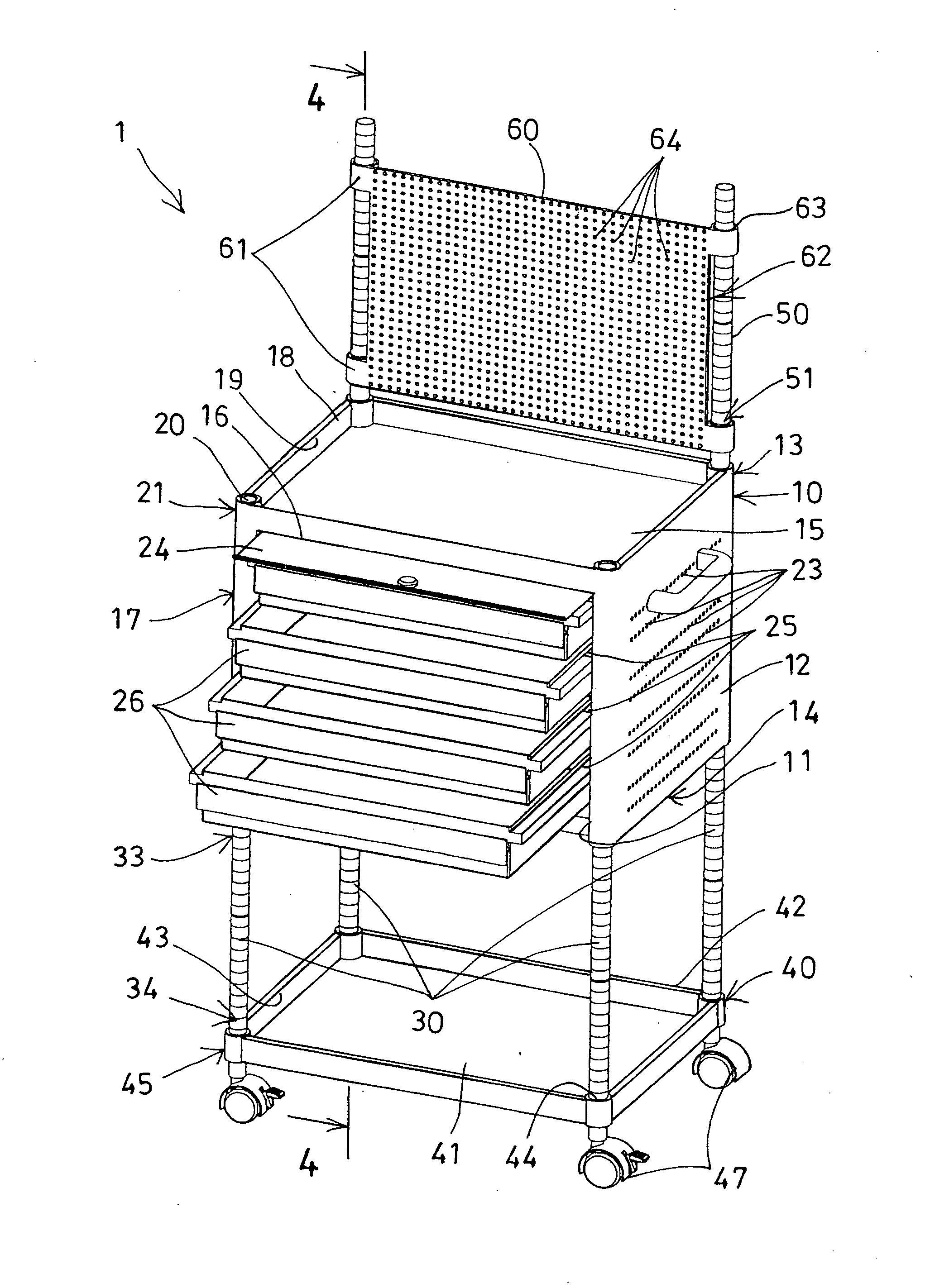
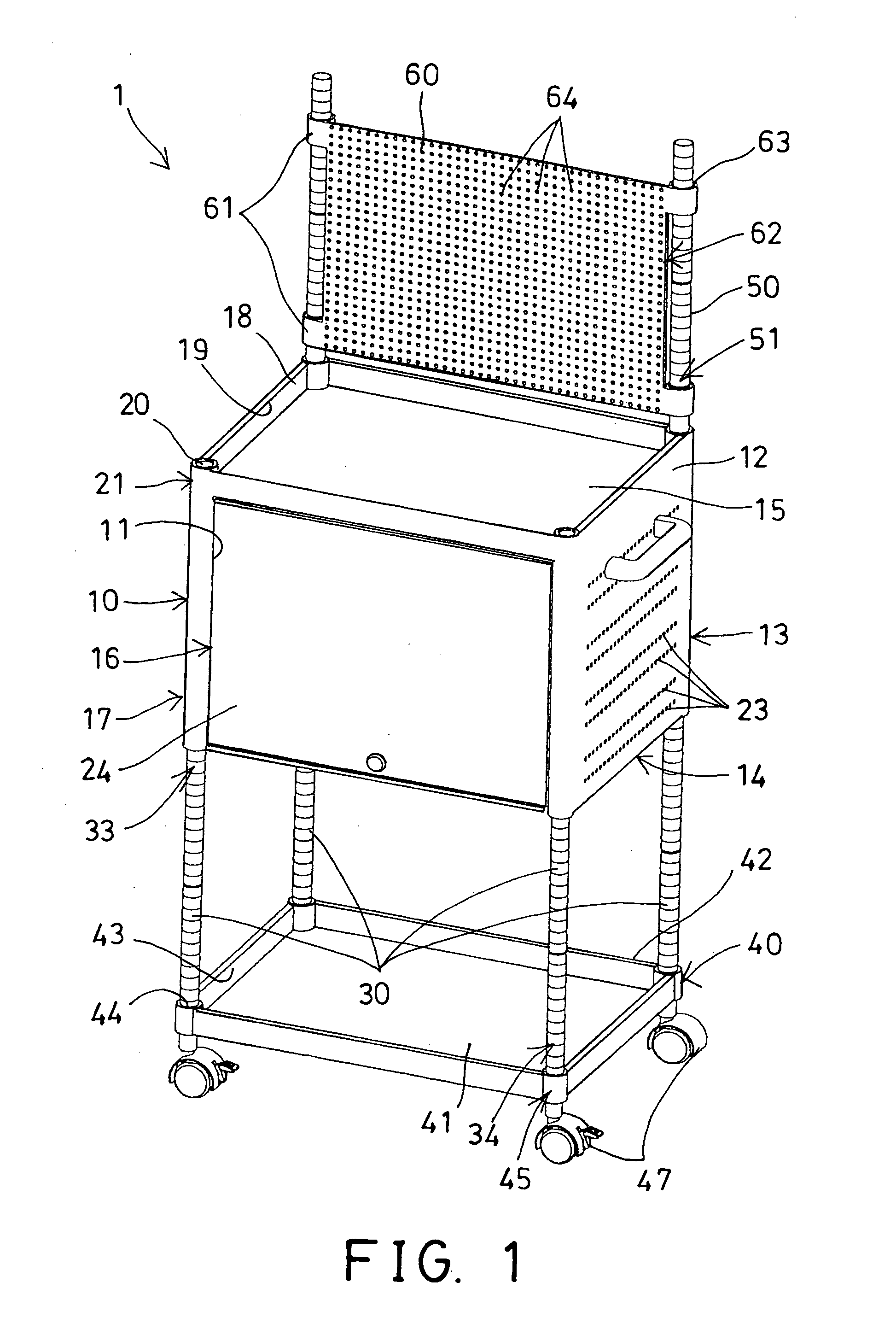
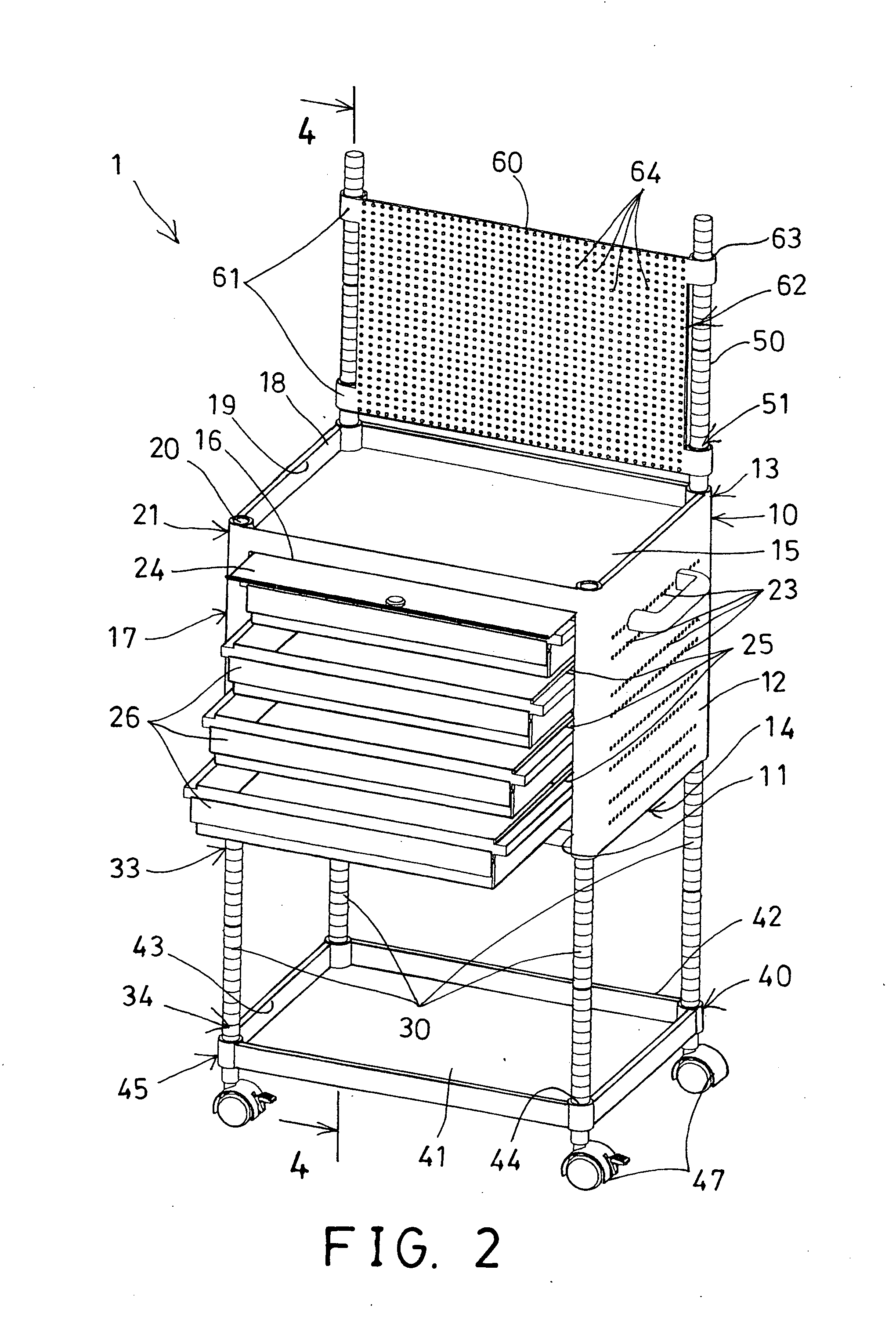
[0023]Referring to the drawings, and initially to FIGS. 1-4, a tool organizing, device 1 in accordance with the present invention comprises an outer housing 10 including a chamber 11 formed therein for receiving various tool members therein (not shown) and formed or defined by two side walls 12, a rear wall 13, a bottom wall 14, and an upper wall 15, and including an opening 16 formed in the front portion 17 thereof and communicative with the chamber 11 of the housing 10, and including a peripheral fence 18 extended upwardly from the outer peripheral portion of the upper wall 15 for forming or defining a recess or compartment 19 above the upper wall 15 and within the peripheral fence 18, and including a cavity 20 formed in each of the four corner areas 21 of the upper wall 15 or the peripheral fence 18 of the housing 10, and including a screw hole or engaging hole 22 (FIG. 4) formed in each of the four corner areas 21 of the bottom wall 14 of the housing 10.

[0024]The housing 10 furt...


PUM


Abstract

A tool organizing device includes a housing having two side walls, a rear wall, a bottom wall, a front opening, and a peripheral fence extended from an upper wall for forming a compartment in the peripheral fence for receiving tool members, and having a number of rails for slidably attaching drawers, and having a number of apertures formed in the side walls for hooking tool members, a tray is selectively and detachably attached to the bottom wall with four posts and includes a peripheral fence extended upwardly from a board for forming a compartment above the board and within the peripheral fence and for receiving tool members, a panel is selectively attached to the housing for hooking tool members.

Description

BACKGROUND OF THE INVENTION[0001]1. Field of the Invention[0002]The present invention relates to a tool organizing device, and more particularly to a tool organizing device including an adjustable structure for suitably storing and displaying or supporting various tool members and for allowing the tool members to be easily and quickly obtained by the users.[0003]2. Description of the Prior Art[0004]Typical tool organizing devices or utility carts comprise one or more shelves attached or mounted or secured onto four corner posts for supporting various tool members or objects, and four casters attached or mounted to the bottom portion of the four corner posts for allowing the utility cart to be moved to the other places or locations.[0005]For example, U.S. Pat. No. 4,595,107 to Welsch discloses one of the typical utility carts comprising one or more drawers or shelves disposed or attached or mounted or secured onto four corner posts which are coupled to two or more handle legs with su...

Claims


Application Information

Patent Timeline
Patent Type & Authority Applications(United States)
IPC IPC(8): A47B81/00A47B88/04A47B96/00A47B97/00
CPCB25H3/028B25H3/06B25H3/04
Inventor CHENG, YING CHOU
Owner CHENG YING CHOU
Why Eureka
Try Eureka