Tunnel monitoring system in a vehicle tunnel

a monitoring system and vehicle tunnel technology, applied in traffic control systems, complex mathematical operations, analog and hybrid computing, etc., can solve the problems of duplicate detection or the practicability of vehicle skipping, and achieve the effect of reducing the cost of installation and avoiding additional safety risks in the tunnel operation

Inactive Publication Date: 2005-08-02
PETERS GODDERT
View PDF9 Cites 5 Cited by
  • Summary
  • Abstract
  • Description
  • Claims
  • Application Information

AI Technical Summary

Benefits of technology

[0017]The ultrasonic sensors can be installed at the tunnel ceiling, whereby a row of functionally interconnected ultrasonic sensors are assigned to the lanes in one direction of travel. Preferably each sensor row is assigned to one single lane as well as to breakdown bays. For easy recognition of stopped vehicles it could also be possible to monitor two lanes in different travel directions with only one row of ultrasonic sensors installed above them. The assignment of a row of ultrasonic sensors to each separate lane in one travel direction results however in considerably more valid monitoring results. It is thereby in particular possible to recognize also a direction of travel so that possible ghost riders can be detected immediately. For an optimal arrangement, the distances between sensors can be up to approximately 10 meters whereby approximately 50 ultrasonic impulses can be emitted and received per second.
[0018]The sensor signals, in particular when also the intensity of the sensor signals is evaluated, must be digitalized in the usual manner for an el...

Problems solved by technology

In addition, only one vehicle can be detected within the emission and receiving zone of an ult...

Method used


Image

  • Tunnel monitoring system in a vehicle tunnel
  • Tunnel monitoring system in a vehicle tunnel
  • Tunnel monitoring system in a vehicle tunnel

Examples


Embodiment Construction

[0027]Referring now to the drawings, the invention will now be described in more detail.

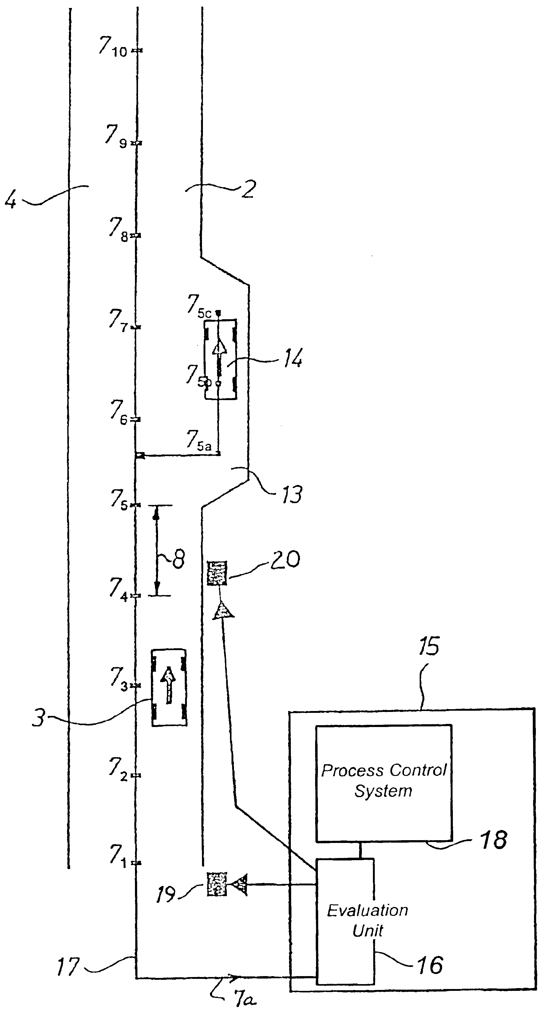
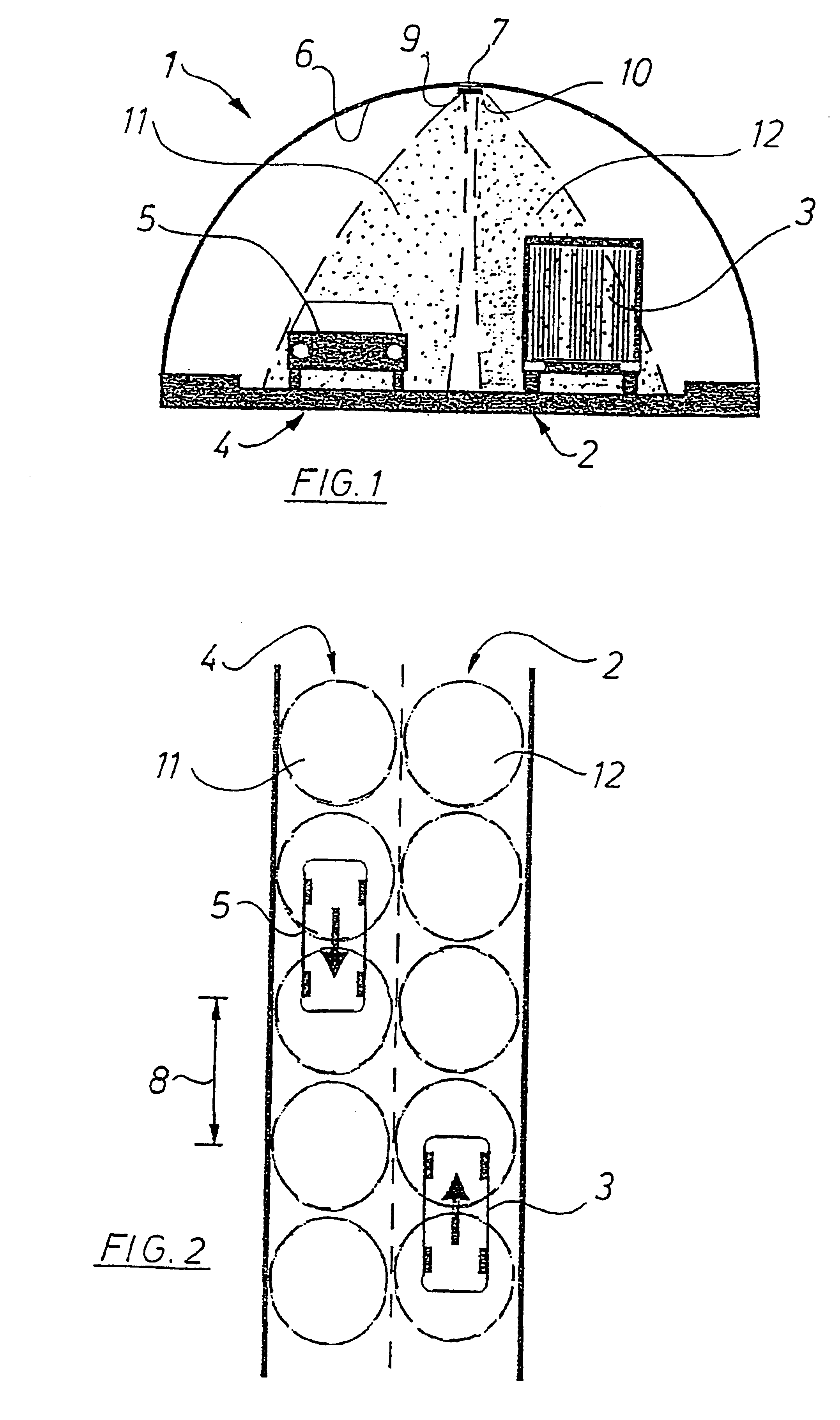
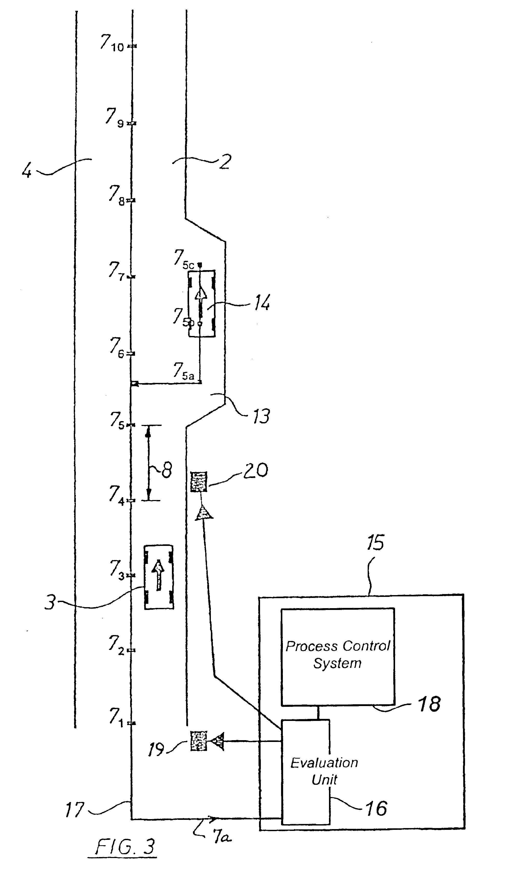
[0028]FIG. 1 illustrates a cross-section through a two-lane tunnel 1 for motor vehicles. A truck 3 is shown schematically on lane 2, on the right side of the tunnel cross-section, and a passenger car 5 is shown on lane 4 in the opposite direction. In a central area of a tunnel ceiling 6 ultrasonic sensor units 7 are installed and are placed at identical distances 8 between sensors in the longitudinal direction of the tunnel 1. Each ultrasonic sensor unit 7 comprises two ultrasonic sensors 9 and 10, these being adjacent to each other, with their respective vehicle detection zone in the illustrated form of a conical emitting and receiving zone 11, 12 directed upon the lane 2 and the lane 4 in opposite lateral directions. As can best be seen in FIG. 1, the vehicle detection zones 11, 12 cover the passing motor vehicles 3 and 5.

[0029]FIG. 2 illustrates a schematic top plan view of FIG. 1 with lane 2 ...


PUM


Abstract

A tunnel monitoring system for monitoring vehicles traveling through a tunnel having at least one vehicle traffic lane is disclosed comprising a plurality of ultrasonic sensors arranged in series in a longitudinal direction of the tunnel. The sensors have a detection zone covering a portion of the traffic lane for detecting the presence of a vehicle in the detection zone, and the ultrasonic sensors generate a vehicle sensor signal upon detecting a vehicle in the detection zone and a sensor identification signal identifying which sensor the sensor signal is transmitted from. The detection zones are projected and arranged in relation to the traffic lane to provide a generally continuous detection of the vehicles traveling though the tunnel. An evaluation unit receives the vehicle sensor signals and the sensor identification signals for monitoring traffic in the tunnel.

Description

BACKGROUND OF THE INVENTION[0001]This invention relates to a tunnel monitoring system for monitoring vehicle traffic in a tunnel.[0002]Tunnel monitoring systems of various designs for monitoring vehicles in a tunnel are generally known. A tunnel monitoring system is known, for example, in which fire reporting devices are installed in the longitudinal direction of the tunnel. This system is designed to detect and locate a possible fire in the tunnel, in particular a burning vehicle. This system can comprise controls actuating automatic warning devices, traffic guiding devices or locking devices in case of a detected fire. Such a monitoring system is suited exclusively for the recognition of dangerous situations due to fire.[0003]Another prior tunnel monitoring system consists of several monitoring cameras installed at intervals along the tunnel. Assigned tunnel segments can be monitored visually, and events detected by a camera are shown on a screen at a tunnel monitoring command sta...

Claims


Application Information

Patent Timeline
IPC IPC(8): G08G1/07G08G1/04G08G1/08G08G1/052G08G1/01E21F11/00
CPCG08G1/04G08G1/052G08G1/08
Inventor PETERS, GODDERT
Owner PETERS GODDERT
Why Eureka
Try Eureka