Imaging device

a technology of imaging device and image, which is applied in the field of imaging device, can solve the problems of low followability to a change of imaging conditions such as a change of subject position, burdening the processing performance of imaging device, and achieving the effect of quick and easy acquisition and favorable image quality

Active Publication Date: 2015-01-08
FUJIFILM CORP
View PDF0 Cites 5 Cited by
  • Summary
  • Abstract
  • Description
  • Claims
  • Application Information

AI Technical Summary

Benefits of technology

[0037]As described above, according to the present invention, a desired image can be quickly and easily obtained with ensured favorable image quality.

Problems solved by technology

However, in these conventional techniques, there are various problems in obtainment of a plurality of images with different characteristics.
Also, since imaging timing varies among the images, followability to a change of imaging conditions such as a change of the position of the subject is low.
Therefore, when only an image with a specific characteristic is desired to be obtained, the obtained image signals have to be separated, thereby putting a burden on processing performance of the imaging device.
Furthermore, the signals are not sufficiently separated to degrade image quality.

Method used


Image

  • Imaging  device
  • Imaging  device
  • Imaging  device

Examples


first embodiment

[0063]

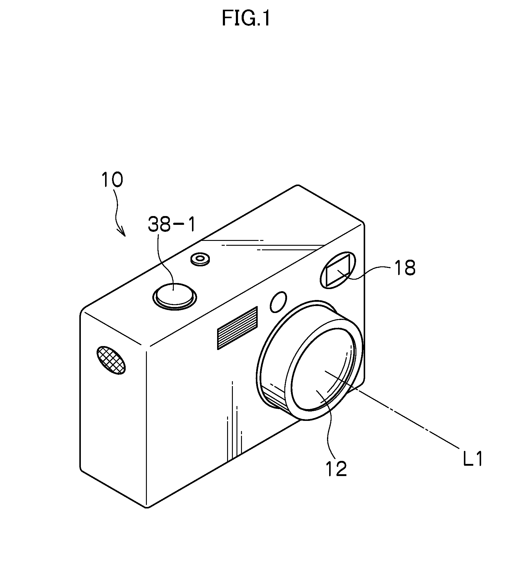
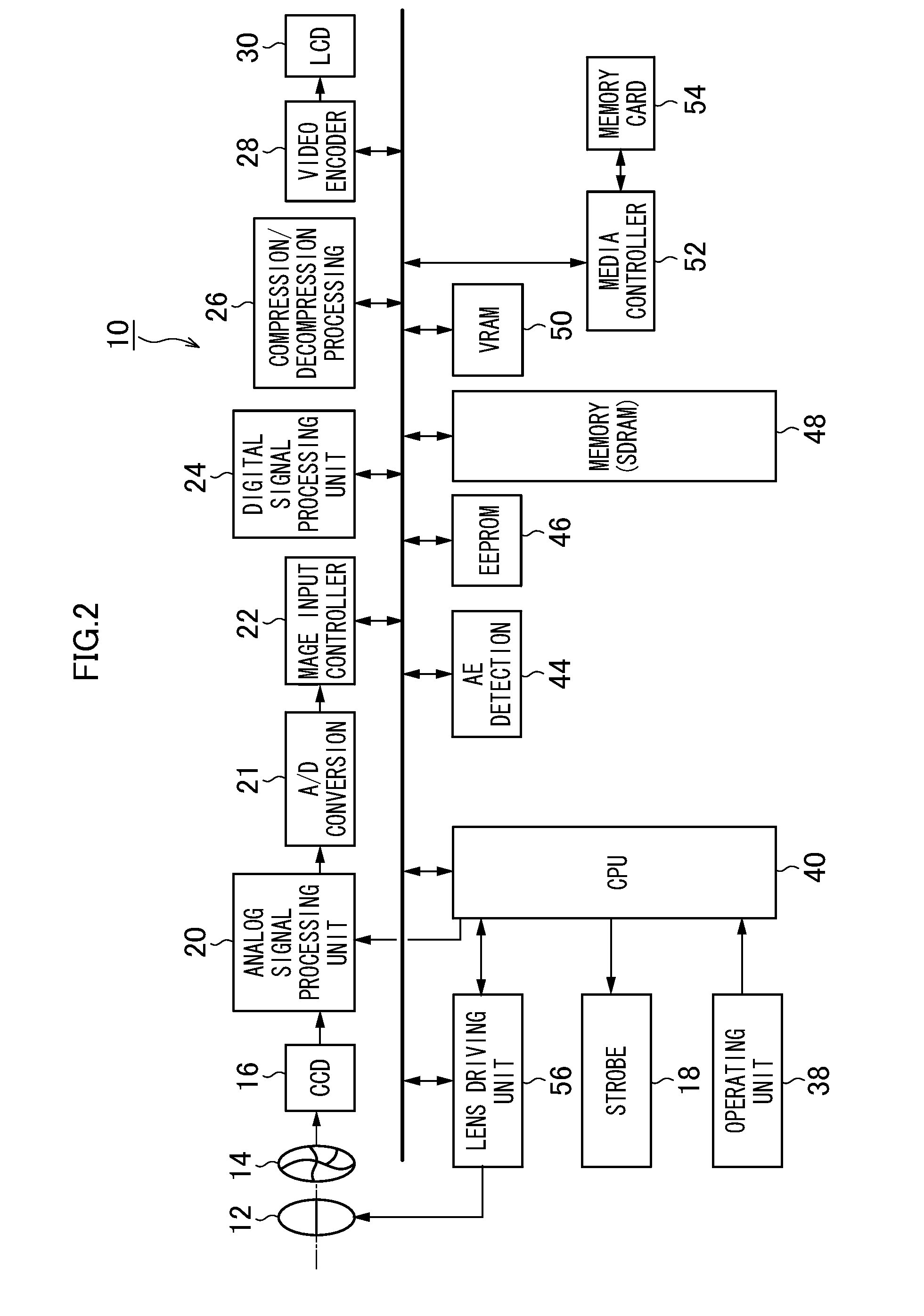
[0064]FIG. 1 is an external perspective view of an imaging device 10 (imaging device) according to a first embodiment of the present invention, and FIG. 2 is a block diagram depicting the structure of main parts of the imaging device 10. As depicted in FIG. 1, the imaging device 10 has a front surface where a taking lens 12, a strobe 18, and so on are arranged and an upper surface where a release button 38-1 is provided. L1 denotes an optical axis of the taking lens 12.

[0065]FIG. 2 is a block diagram depicting depicting the structure of main parts of the imaging device 10. The operation of the entire imaging device 10 is controlled in a centralized manner by a central processing unit (CPU) 40, and programs (including programs for use in image generation / combing processing, which will be described further below) and parameters are stored in an EEPROM (Electronically Erasable and Programmable Read Only Memory) 46.

[0066]The imaging device 10 is provided with an operating unit 38 ...

second embodiment

[0115]

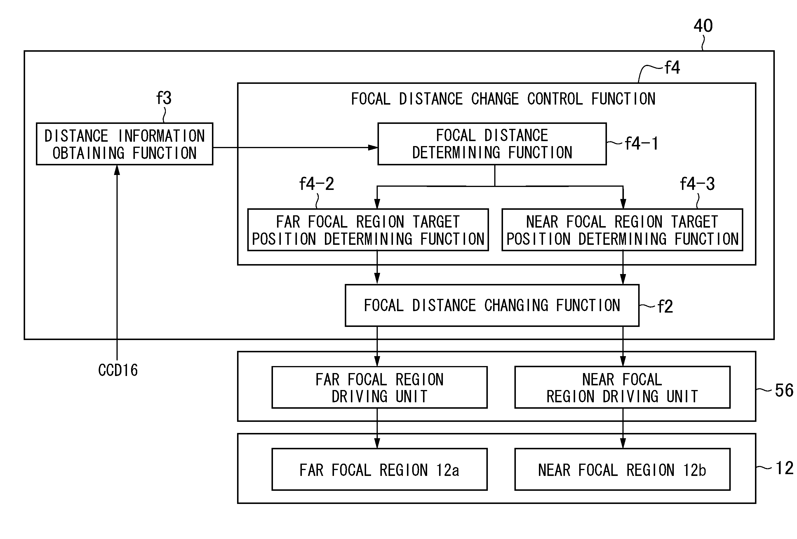
[0116]Next, a second embodiment of the imaging device according to the present invention is described. While the focal distance is changed based on the user operation or instruction input in the first embodiment described above, the case is described in the second embodiment in which the focal distance is automatically changed based on a distribution of a subject distance.

[0117]Also in the second embodiment, the basic structure of the imaging device is similar to that of the first embodiment, and therefore differences are described below. FIG. 15 is a diagram of a functional structure of a CPU in the second embodiment. In the second embodiment, the CPU 40 has the following functions f1 to f4.

[0118]As with the first embodiment, the image generation / combining function f1 is a function of generating images each corresponding to the focal distance and the focal length in each region of the taking lens 12 by using imaging signals outputted from the CCD 16 and generating an image ob...

third embodiment

[0125]Next, a third embodiment of the imaging device according to the present invention is described. While the cases have been described in the first and second embodiments described above in which the focal distances of the respective regions of the taking lens are different from each other and the focal distance is changed, the cases are described in the third embodiment in which the focal distances of the respective regions of the taking lens are equal to each other and the focal length is changed.

[0126]Since the imaging device according to the third embodiment is basically similar to those of the first and second embodiments (refer to FIG. 2), differences are described below.

[0127]A taking lens 12′ in the imaging device according to the third embodiment has a first region 12a′ and a second region 12b′, and these regions are at an equal focal distance and with different focal lengths (image magnifications). And, these two focal regions act as two lenses physically separated from...


PUM


Abstract

An imaging device according to one mode of the present invention includes a taking lens formed of two or more physically separated lenses and having a plurality of regions each having an individual focal distance corresponding to a combination of the two more lenses, an image pickup element having a plurality of light-receiving sensors provided to correspond to the plurality of regions, the plurality of light-receiving sensors each selectively receiving a light beam passing through any of the plurality of regions, and an image generating unit which generates an image of a subject from an imaging signal outputted from the image pickup element.

Description

CROSS-REFERENCE TO RELATED APPLICATIONS[0001]This application is a Continuation of PCT International Application No. PCT / JP2013 / 0055793 filed on Mar. 4, 2013, which claims priority under 35 U.S.C §119(a) to Japanese Patent Application No. 2012-63840 filed on Mar. 21, 2012. Each of the above application(s) is hereby expressly incorporated by reference, in its entirety, into the present application.BACKGROUND OF THE INVENTION[0002]1. Field of the Invention[0003]The present invention relates to imaging devices and, in particular, to an imaging device capable of obtaining a plurality of images with different characteristics.[0004]2. Description of the Related Art[0005]In the field of imaging devices, a technique has been known in which a plurality of images with different characteristics are obtained by imaging a plurality of times with varied imaging conditions or using lens systems having a plurality of characteristics and the obtained images are processed according to the purpose (fo...

Claims


Application Information

Patent Timeline
Patent Type & Authority Applications(United States)
IPC IPC(8): G02B7/02H04N5/232
CPCH04N5/23212G02B7/021G03B17/12G03B5/02G03B15/00G03B2205/00H04N23/67H04N23/631
Inventor ONO, SHUJI
Owner FUJIFILM CORP
Why Eureka
Try Eureka