Onboard unit controlling apparatus

a unit control and unit control technology, applied in the direction of dashboard fitting arrangements, instruments, transportation and packaging, etc., can solve the problems of troublesome operation of the switch, difficult installation space for the switch, and the inability of the occupant to judge which onboard unit can be operated now by the switch, so as to prevent a common switch

Inactive Publication Date: 2010-12-23
HONDA MOTOR CO LTD
View PDF14 Cites 32 Cited by
  • Summary
  • Abstract
  • Description
  • Claims
  • Application Information

AI Technical Summary

Benefits of technology

[0008]The present invention has been made in view of the foregoing situation, and an object of the present invention is to reliably prevent a common switch from mistakenly operating one of mutually-adjacent onboard units when the common switch takes a role of operating multiple onboard units.
[0010]According to the configuration of the first feature, when the occupant's sight line detected by the sight line detecting means is directed to any one of the multiple onboard units, the control means allows the onboard unit, to which the sight line is directed, to be operable. Thus, the occupant can select the onboard unit which the occupant wishes to operate without using the hand. This enhances the convenience of the occupant or operator. In addition, the notice means informs the occupant that the onboard unit, to which the sight line is directed, is operable. Accordingly, the occupant can avoid operating a wrong onboard unit while reliably recognizing the operable onboard unit even if the multiple onboard units are arranged close to one another.
[0012]According to the configuration of the second feature, the notice means are luminous bodies, each of which is provided to a corresponding one of the onboard units, and each of which emits light when the onboard unit is operable. This makes it possible for the occupant to reliably recognize the operable onboard unit.
[0014]According to the configuration of the third feature, any one of the operable onboard units is operated by the steering switch installed in the steering wheel. Thus, the occupant can operate the onboard unit without releasing the hands from the steering wheel. This enhances the convenience of the operator / occupant. Furthermore, because the functions of the steering switch are switched from one to another depending on the operable onboard unit, the occupant can operate the multiple onboard units by the common steering switch. This helps to reduce the number of installation spaces and component parts, and to improve the operability.
[0016]According to the configuration of the fourth feature, while the vehicle is running, if any one of the onboard units continues to be operable longer than a predetermined time, the operable state of one onboard unit is cancelled. Thus, the occupant can avoid a mistake of not paying sufficient attention to the front view, the mistake made by fixing the sight line to one onboard unit for a long time. Moreover, the operation mode of the notice means changes once the operable state of the onboard unit is cancelled. Thus, the occupant can reliably recognize when the onboard unit becomes inoperable.

Problems solved by technology

However, when each of the multiple onboard units is operated by the corresponding switch, a large number of switches are required, which in turn causes problems that securing installation spaces for switches is difficult, and that operations of the switches are troublesome.
However, in the above case, if the multiple onboard units are arranged close to one another, the occupant cannot judge which onboard unit can be operated now by the switch.
As a result, the occupant may mistakenly operate an onboard unit different from the onboard unit which the occupant wishes to operate.

Method used


Image

  • Onboard unit controlling apparatus
  • Onboard unit controlling apparatus
  • Onboard unit controlling apparatus

Examples


first embodiment

[0037]Now, the present invention will be described below based on FIGS. 1 to 18.

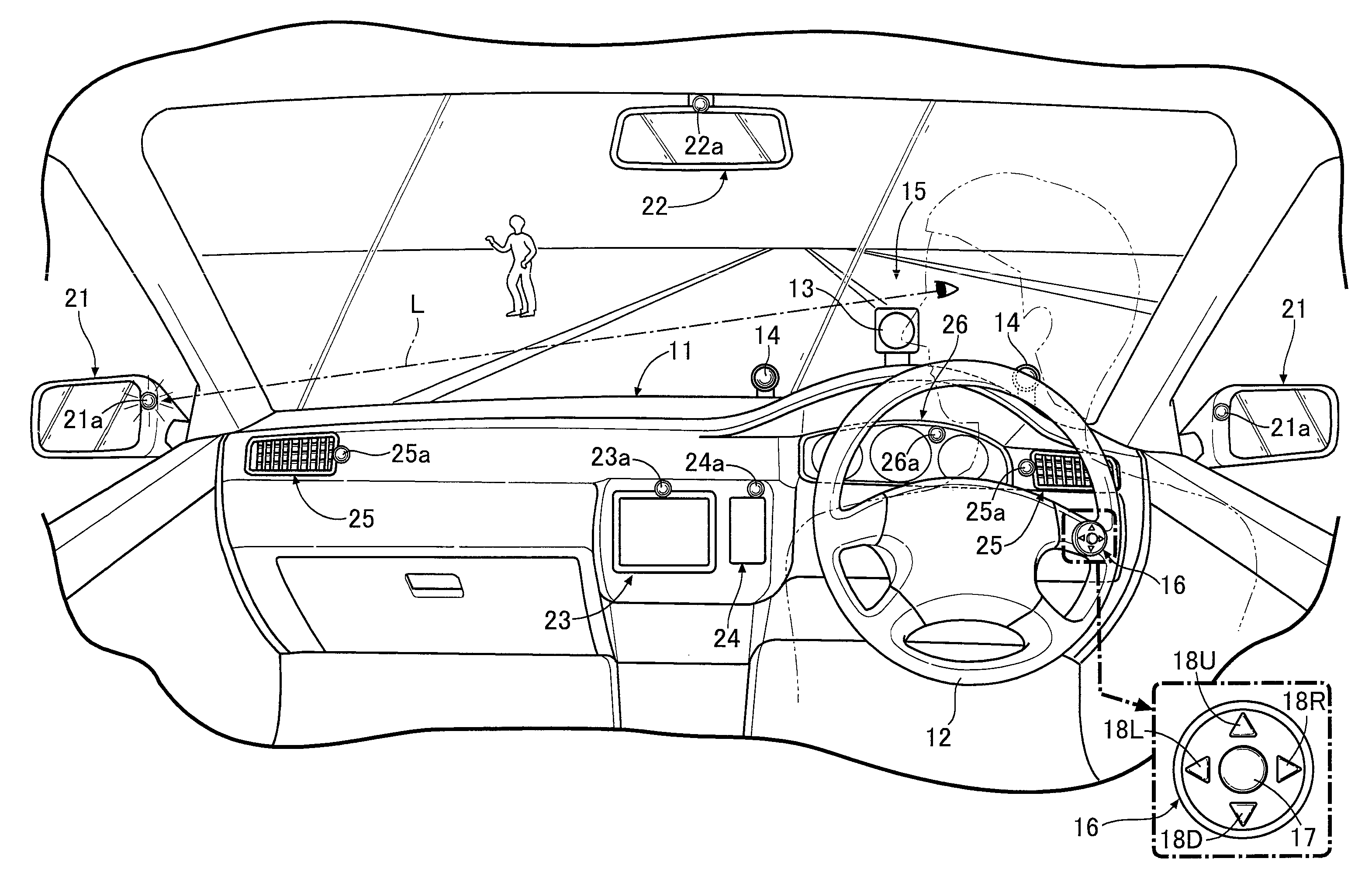
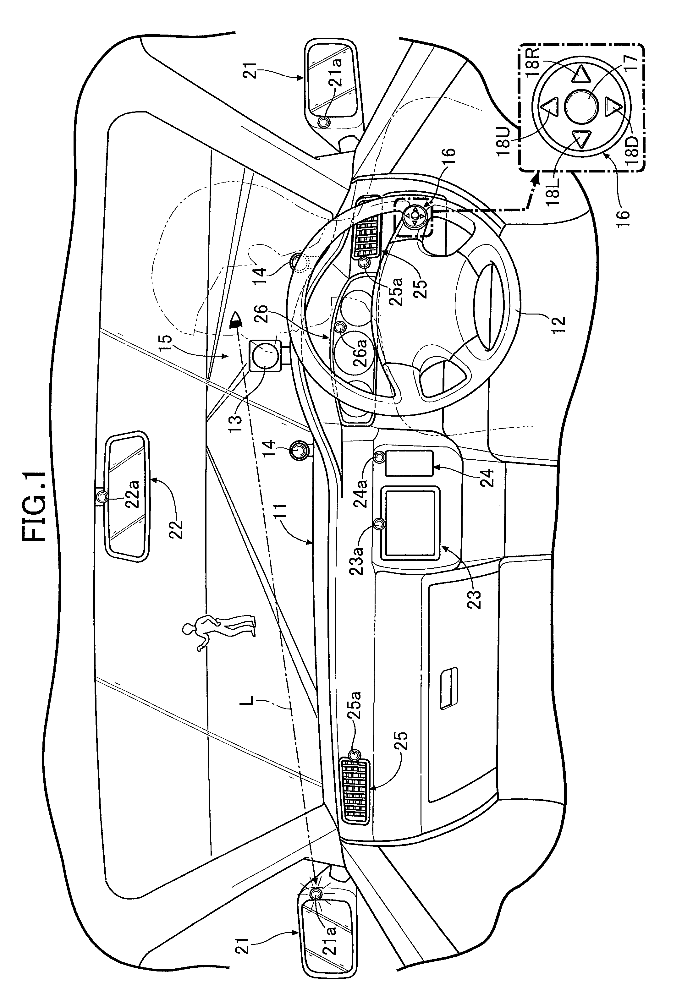
[0038]As shown in FIG. 1, a steering wheel 12 is placed in the right of an instrumental panel 11 of an automobile. A near-infrared camera 13 and pair of near-infrared LEDs 14, 14 are installed on the instrumental panel 11 in front of the steering wheel 12. The pair of near-infrared LEDs 14, 14 are respectively situated on the left and right sides of the near-infrared camera 13. The near-infrared camera 13 and the near-infrared LEDs 14, 14 serve as a sight line detector 15 configured to detect a direction in which an occupant casts the sight line L.

[0039]The sight line detector 15 is configured as follows. The pair of near-infrared LEDs 14, 14 emit their respective beams of near-infrared light. An image of a reflecting point on each eyeball off which the beams of near-infrared light is reflected and the center of the pupil of each eyeball is captured by the near-infrared camera 13. Thereby, the sight line...

second embodiment

[0067]Next, descriptions will be provided for the present invention.

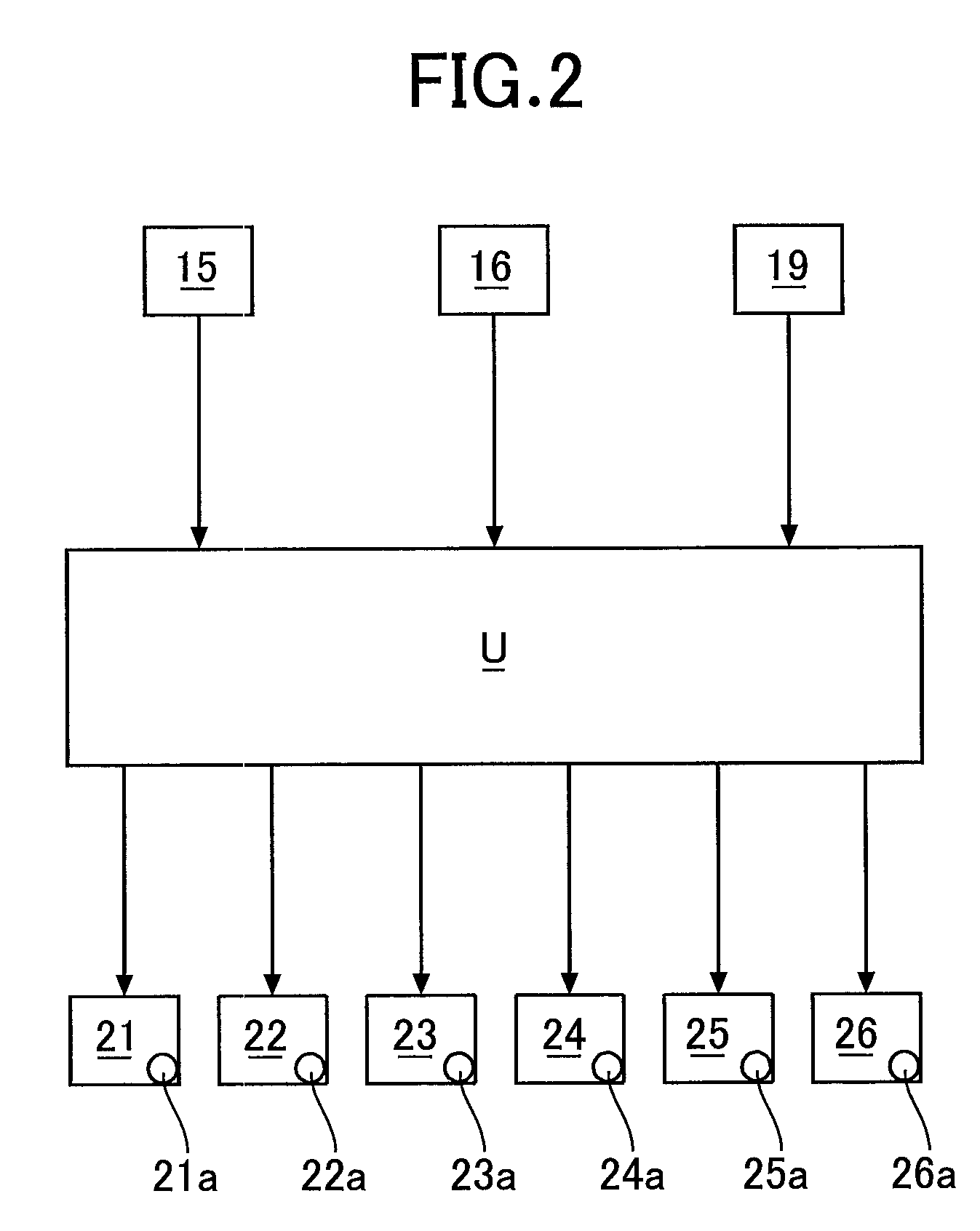
[0068]The second embodiment is the onboard unit controlling apparatus which employs the vehicle speed detector 19 (see FIG. 2). While the vehicle speed detector 19 is detecting that the vehicle is running, if any one of the onboard units continues to be operable (or any one of the pilot lamps continues to be on) longer than a predetermined time, there is a risk that: the sight line L of the occupant may have been cast on the onboard unit for a long time; and the occupant may pay insufficient attention to the front view.

[0069]With this taken into consideration, once the predetermined time has passed, the second embodiment switches the onboard unit from an operable state to an inoperable state, and concurrently switches the pilot lamp from on to flashing or off. Thereby, the second embodiment notifies or informs the occupant that the onboard unit is inoperable. This enables the occupant to return the sight line L to t...


PUM


Abstract

When an occupant's sight line detected by sight line detector is directed to any one of multiple onboard units (a side mirror, a rear view mirror, a navigation system, an in-vehicle phone, an air blowout port, and a meter panel), a controller allows the onboard unit, to which the sight line is directed, to be operable. Thus, the occupant can select the onboard unit, which the occupant wishes to operate, by the sight line without using the hand and further can operate the onboard unit by use of a common steering switch, thereby enhancing the convenience of operation. In addition, a corresponding one of pilot lamps notifies the occupant that the corresponding one of the onboard units, to which the sight line is directed, is operable. Accordingly, the occupant can avoid operating a wrong onboard unit while reliably recognizing the operable onboard unit even if the multiple onboard units are arranged close to one another.

Description

BACKGROUND OF THE INVENTION[0001]1. Field of the Invention[0002]The present invention relates to an onboard unit controlling apparatus including: a plurality of onboard units operable by an occupant; sight line detecting means configured to detect a sight line of the occupant; and control means configured such that, when the sight line of the occupant detected by the sight line detecting means is directed to any one of the plurality of onboard units, the control means turns the onboard unit, to which the sight line is directed, into an operable state.[0003]2. Description of the Related Art[0004]Japanese Patent Application Laid-open No. 2007-38790 discloses an apparatus that adjusts the direction of each of the left and right side mirrors of an automobile. In this publication the apparatus is configured to: capture an image of an occupant's face by use of a camera; judge which of the left and right side mirrors the occupant turns the face to; adjust the left side mirror upward, downw...

Claims


Application Information

Patent Timeline
Patent Type & Authority Applications(United States)
IPC IPC(8): G06F19/00G06F17/00B60R11/04B60R16/02G06F3/033G06F3/0346
CPCB60K37/06B60K2350/96B60K2350/2013B60K2350/1008B60K2370/12B60K2370/18B60K2370/21
Inventor TAKAHASHI, AKIOUEDA, SHINSUKE
Owner HONDA MOTOR CO LTD
Why Eureka
Try Eureka