Surgical Tool

a surgical tool and tool body technology, applied in the field of surgical tools, can solve the problems of reducing the ability affecting the integrity of the implanted object, and causing the patient to be jarred

Inactive Publication Date: 2011-03-17
WARSAW ORTHOPEDIC INC
View PDF19 Cites 792 Cited by
  • Summary
  • Abstract
  • Description
  • Claims
  • Application Information

AI Technical Summary

Problems solved by technology

Moreover, most of the components used in the surgery are rigid components that must be physically manipulated by a surgeon while in the patient (i.e., in-situ) leading to potential physical harm to the patient as some of the procedures can result in substantial jarring of the patient including for example, shearing off the head portions of set screws for permanent placement.
Additionally, such manipulation by a surgeon may also compromise the integrity of the implanted object lessening its capabilities.
Given the delicacy of surgical procedures and the anatomical importance of the spine, jarring of the patient during such surgical procedures is inherently dangerous.
Additionally, the vast majority of these surgical procedures are completed by handheld manual tools, meaning hours of rigorous work for a surgeon to implant all the screws and properly align the spine with an implanted rod.

Method used


Image

  • Surgical Tool
  • Surgical Tool
  • Surgical Tool

Examples


Embodiment Construction

Description of Relevant Anatomy

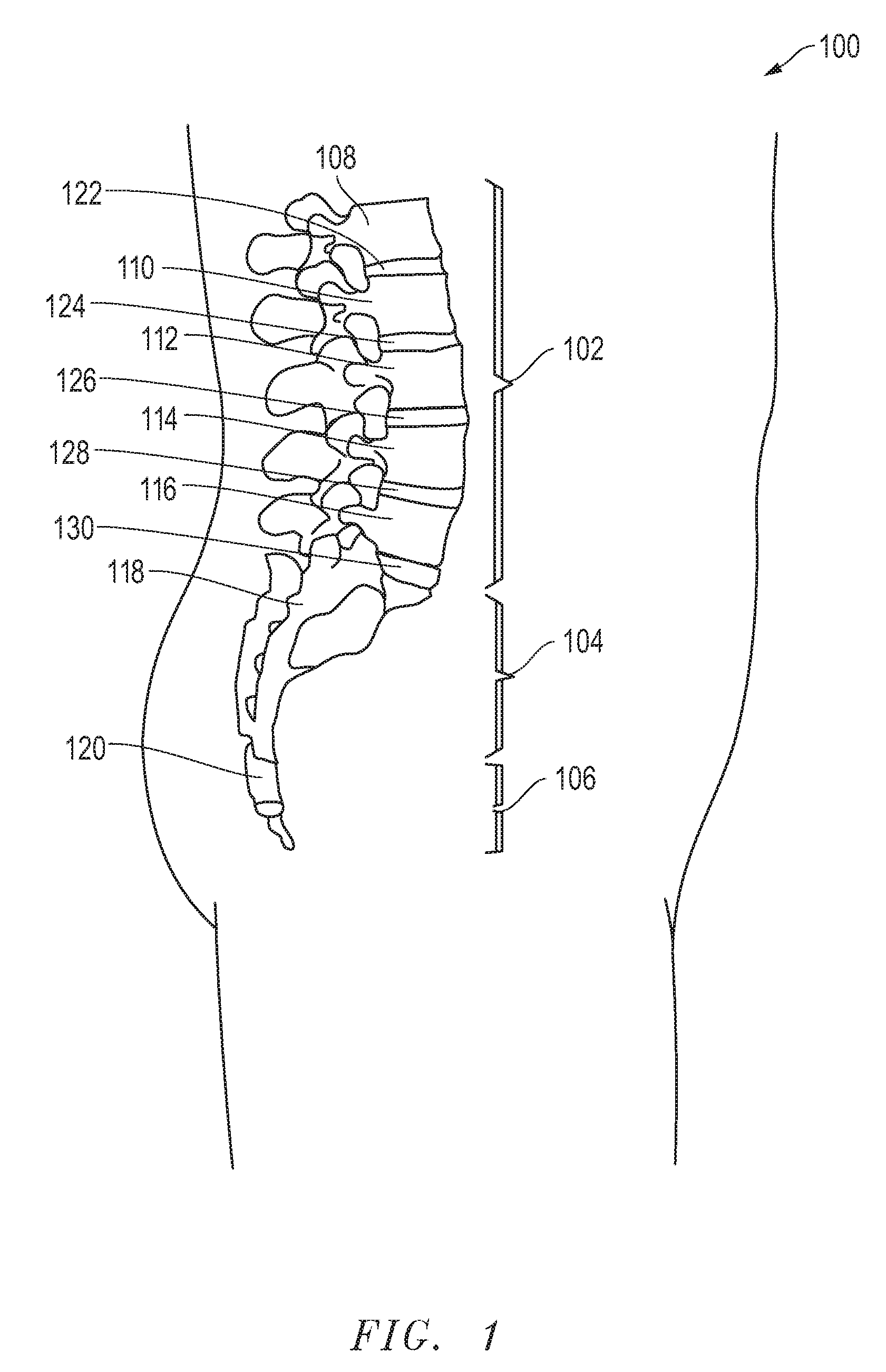
[0039]Referring initially to FIG. 1, a portion of a vertebral column, designated 100, is shown. As depicted, the vertebral column 100 includes a lumbar region 102, a sacral region 104, and a coccygeal region 106. The vertebral column 100 also includes a cervical region and a thoracic region. For clarity and ease of discussion, the cervical region and the thoracic region are not illustrated.

[0040]As illustrated in FIG. 1, the lumbar region 102 includes a first lumbar vertebra 108, a second lumbar vertebra 110, a third lumbar vertebra 112, a fourth lumbar vertebra 114, and a fifth lumbar vertebra 116. The sacral region 104 includes a sacrum 118. Further, the coccygeal region 106 includes a coccyx 120.

[0041]As depicted in FIG. 1, a first intervertebral lumbar disc 122 is disposed between the first lumbar vertebra 108 and the second lumbar vertebra 110. A second intervertebral lumbar disc 124 is disposed between the second lumbar vertebra 110 and the third...


PUM


Abstract

A surgical tool for removing a portion of an implant is provided that includes a housing, a motor contained within the housing and coupled to the housing, and an output shaft having a distal end and a proximal end opposite the distal end, wherein the proximal end is coupled to the motor and the distal end has an opening configured to rotateably engage an implant. The surgical tool further includes a counter-torque sleeve extending around the output shaft having a proximal end and a distal end opposite the proximal end, wherein the proximal end is coupled to the housing and the distal end is configured to couple to the implant relative to the counter-torque sleeve. Upon a rotational force to the implant, the forces transmitted by the output shaft and the counter-torque sleeve are balanced by the coupling of the output shaft and counter-torque sleeve through the housing.

Description

BACKGROUND[0001]1. Field of the Disclosure[0002]This disclosure is directed to a surgical tool, and more particularly directed toward a surgical tool for removing a portion of an implant.[0003]2. Description of the Related Art[0004]There are a variety of different spinal diseases, such as scoliosis, as well as others, which may be cured or mitigated by implantation of certain devices. Such devices can include articles and mechanisms useful for repairing damaged portions of the spine, stabilizing portions of the spine, or changing the position of the spine to a more healthy state. For example, rod and anchor systems are commonly employed when portions of the spine need to be realigned, such as in patients with abnormal curvatures, wherein the rod provides rigid support for urging the spine to a more healthy position.[0005]Typically, the process of implanting rod and anchor systems can be quite daunting, including the implantation of multiple anchors or bone screws within particular l...

Claims


Application Information

Patent Timeline
Patent Type & Authority Applications(United States)
IPC IPC(8): A61B17/58
CPCA61B17/7091A61B17/8863A61B2017/00017H01M2/1055A61B2017/00384A61B2019/307A61B2017/00128A61B2090/037H01M50/213Y02E60/10
Inventor MCGAHAN, THOMAS V.BHARADWAJ, JEETENDRA S.COBURN, CALEB J.MEYERS, PAUL F.
Owner WARSAW ORTHOPEDIC INC
Why Eureka
Try Eureka