Battery Energy Source Arrangement And Voltage Source Converter System

a voltage source converter and energy source technology, applied in the direction of dc network circuit arrangement, transportation and packaging, ac network load balancing, etc., can solve the problems of parallel-connected battery strings not running in optimal fashion, capacity redundancy, and charge redistribution, so as to prolong improve the service life and prevent voltage differences due to performance variations of individual cells of the battery energy storage.

a voltage source converter and energy source technology, applied in the direction of dc network circuit arrangement, transportation and packaging, ac network load balancing, etc., can solve the problems of parallel-connected battery strings not running in optimal fashion, capacity redundancy, and charge redistribution, so as to prolong improve the service life and prevent voltage differences due to performance variations of individual cells of the battery energy storage.

US20110089763A1Active Publication Date: 2011-04-21HITACHI ENERGY SWITZERLAND AG

Image

  • Battery Energy Source Arrangement And Voltage Source Converter System
  • Battery Energy Source Arrangement And Voltage Source Converter System
  • Battery Energy Source Arrangement And Voltage Source Converter System

Examples


Embodiment Construction

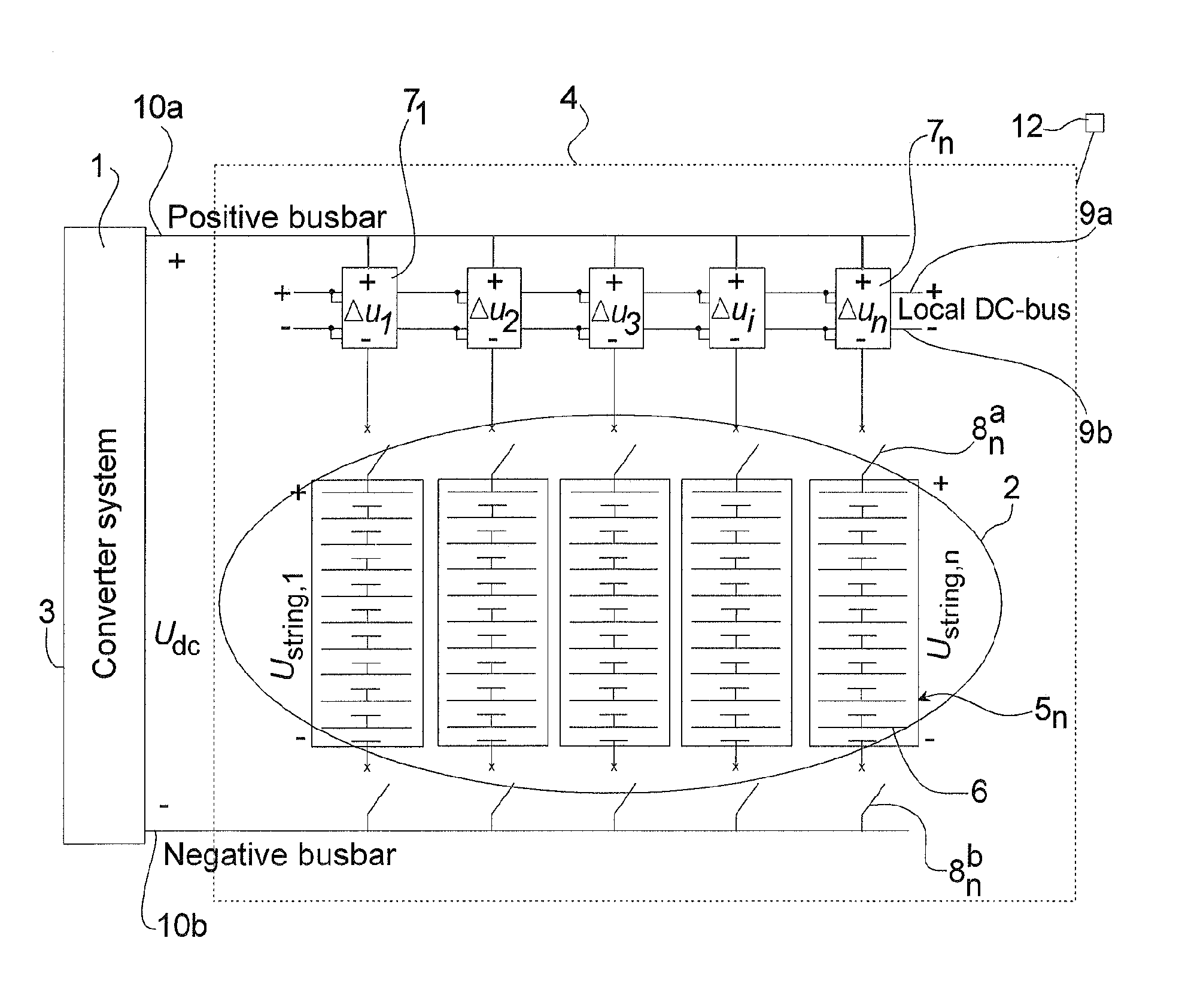
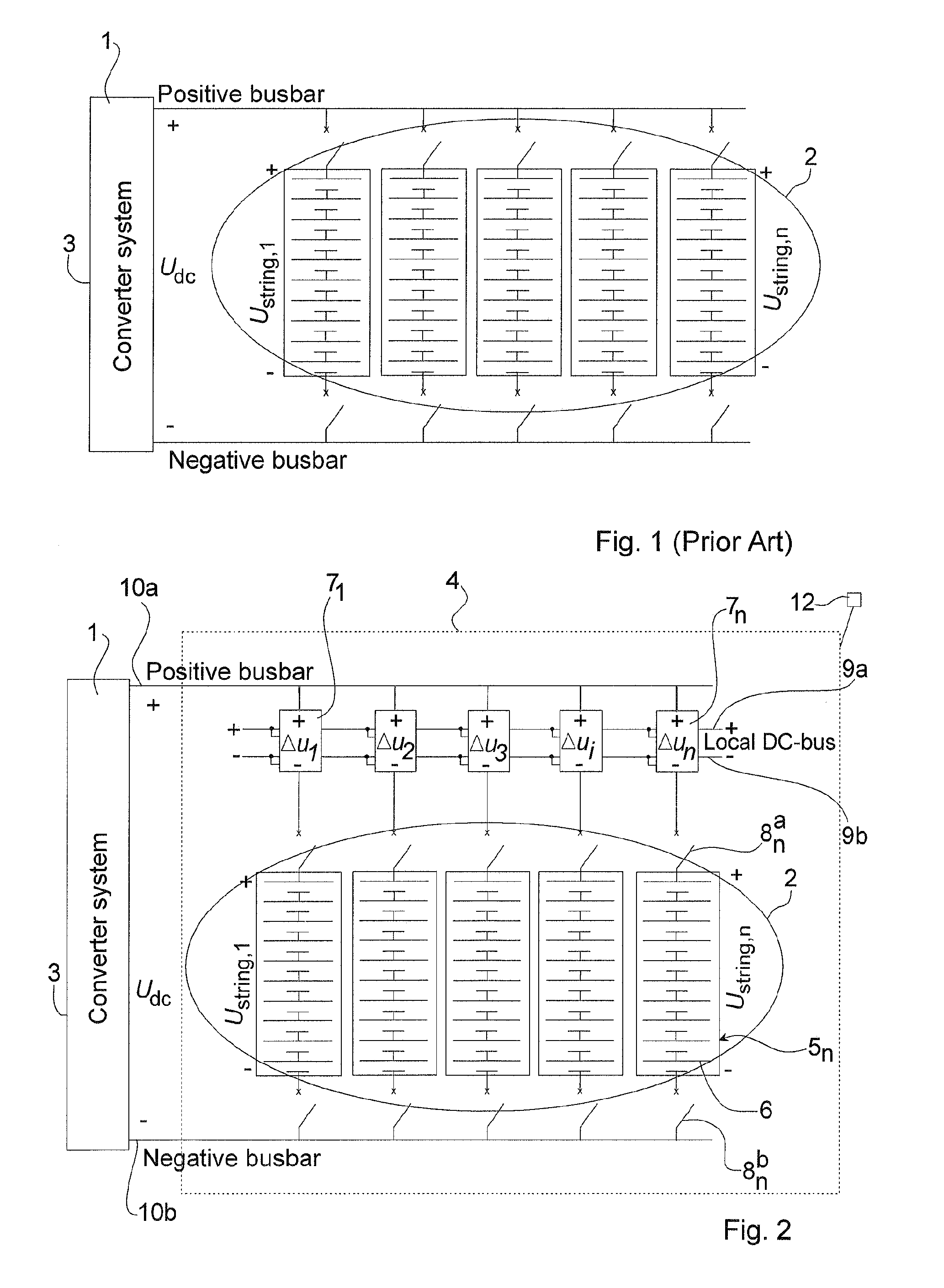
[0025]FIG. 2 illustrates an embodiment of the invention. The same reference numerals are used throughout the figures for same or corresponding parts.

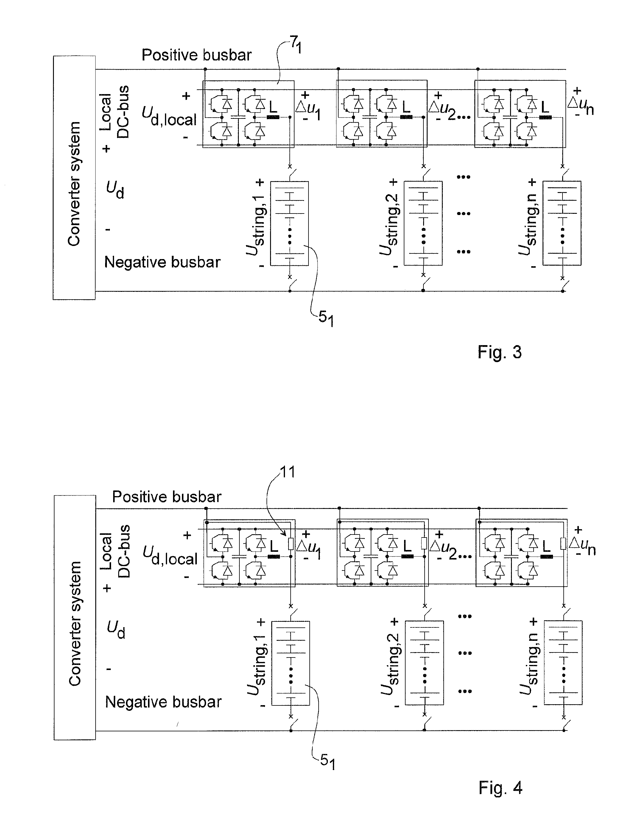
[0026]A battery energy source arrangement 4 in accordance with the invention comprises connection means for being connected in parallel with a voltage source converter 1 and further comprises a battery energy storage 2, preferably comprising lithium ion batteries, and battery string voltage adapter devices 7i, in the following denoted adapter devices 7i.

[0027]The battery energy storage 2 comprises one or more battery strings 51, . . . , 5i, . . . , 5n connected electrically in parallel across common busbars 10a, 10b. Each battery string 51, . . . , 5i, . . . , 5n comprises series connected battery modules, wherein each battery module comprises battery cells 6, having any suitable nominal individual voltage, for example 3.4 V. Further, any suitable number of battery cells 6 can be connected electrically in series giving a suitable nomina...


PUM


Abstract

The invention relates to power networks, and in particular to a battery energy source arrangement and voltage source converter system in such network. The battery energy source arrangement includes battery energy storage, having one or more parallel-connected battery strings and a mechanism for connecting a voltage of the battery strings to a load. The battery energy source arrangement further includes battery string voltage adapter devices connected in series with respective ones of the one or more battery strings wherein the battery string voltage adapter devices are designed to handle only a fraction of the voltage handled by the battery strings.

Description

CROSS-REFERENCE TO RELATED APPLICATIONS[0001]The present application is a continuation of pending International patent application PCT / EP2008 / 058247 filed on Jun. 27, 2008, which designates the United States and the content of which is incorporated herein by reference.FIELD OF THE INVENTION[0002]The invention relates generally to the field of electric power transmission networks, and in particular to active power support in power transmission networks.BACKGROUND OF THE INVENTION[0003]It is sometimes advantageous to be able to control not only the reactive power, but also to inject or absorb active power, also denoted real power. The STATCOM can therefore be provided with an energy source on its DC side in order to provide some active power, in addition to the reactive power generated to the network. For example, the real power can be utilized either as a source of reserve power when an energy deficit occurs within the network, or as a control power for managing transients and electr...

Claims


Application Information

Patent Timeline
21 Apr 2011
Publication
US20110089763A1
IPC
H02J7/34
CPC
H02J3/32; H02J3/38; H02M7/797; H02J7/34; Y02E40/10
Inventors
SVENSSON, JAN R.; DEMETRIADES, GEORGIOS