Directional drilling control using periodic perturbation of the drill bit

a directional drilling and control technology, applied in the direction of directional drilling, earth drilling and mining, drilling machines and methods, etc., can solve problems such as complicated directional drilling

a directional drilling and control technology, applied in the direction of directional drilling, earth drilling and mining, drilling machines and methods, etc., can solve problems such as complicated directional drilling

US20110108327A1Inactive Publication Date: 2011-05-12PRECISION ENERGY SERVICES

Image

  • Directional drilling control using periodic perturbation of the drill bit
  • Directional drilling control using periodic perturbation of the drill bit
  • Directional drilling control using periodic perturbation of the drill bit

Examples


Embodiment Construction

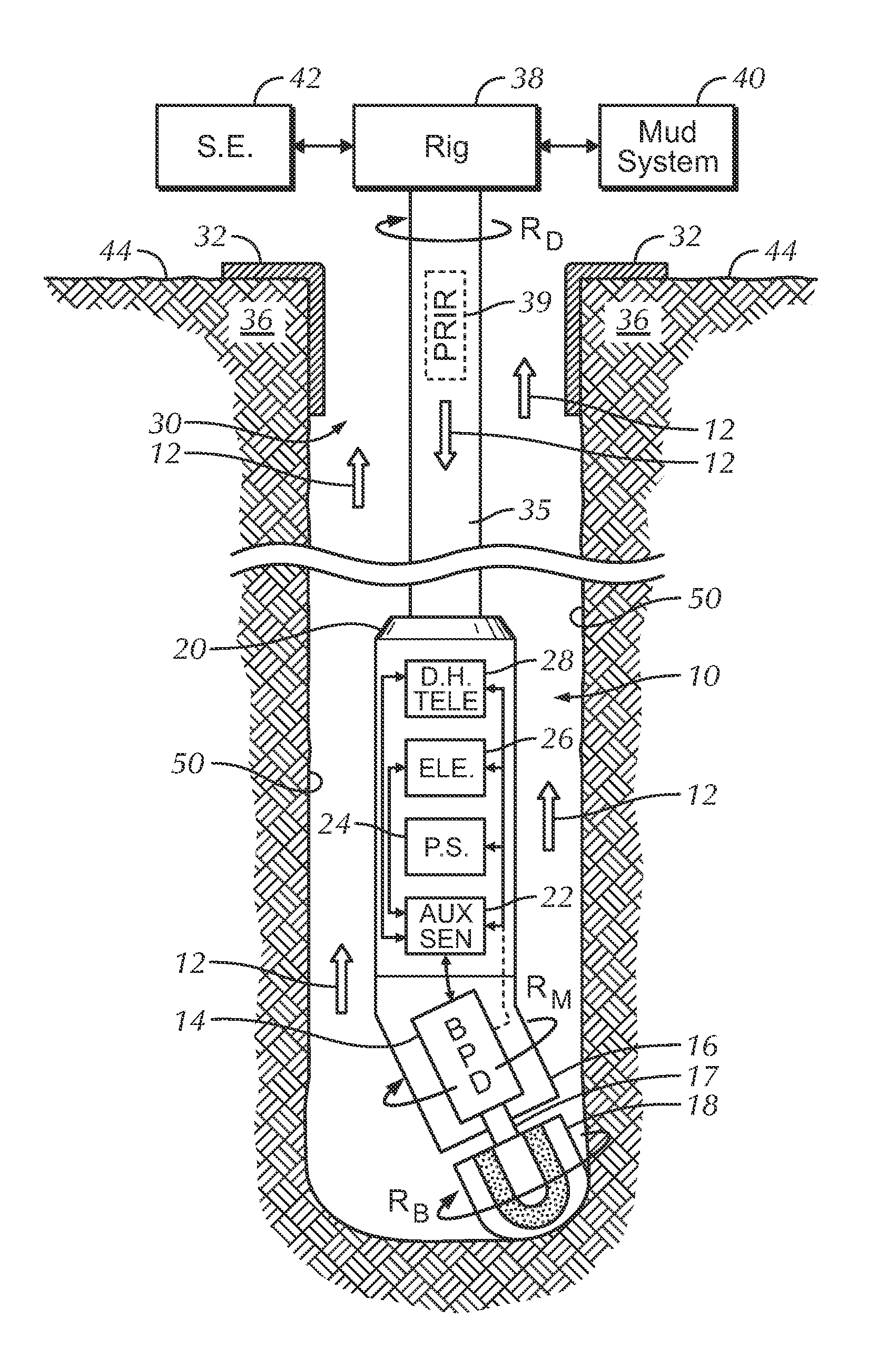
[0021]Disclosed herein are devices and methods for steering the direction of a borehole advanced by cutting action of a rotary drill bit.

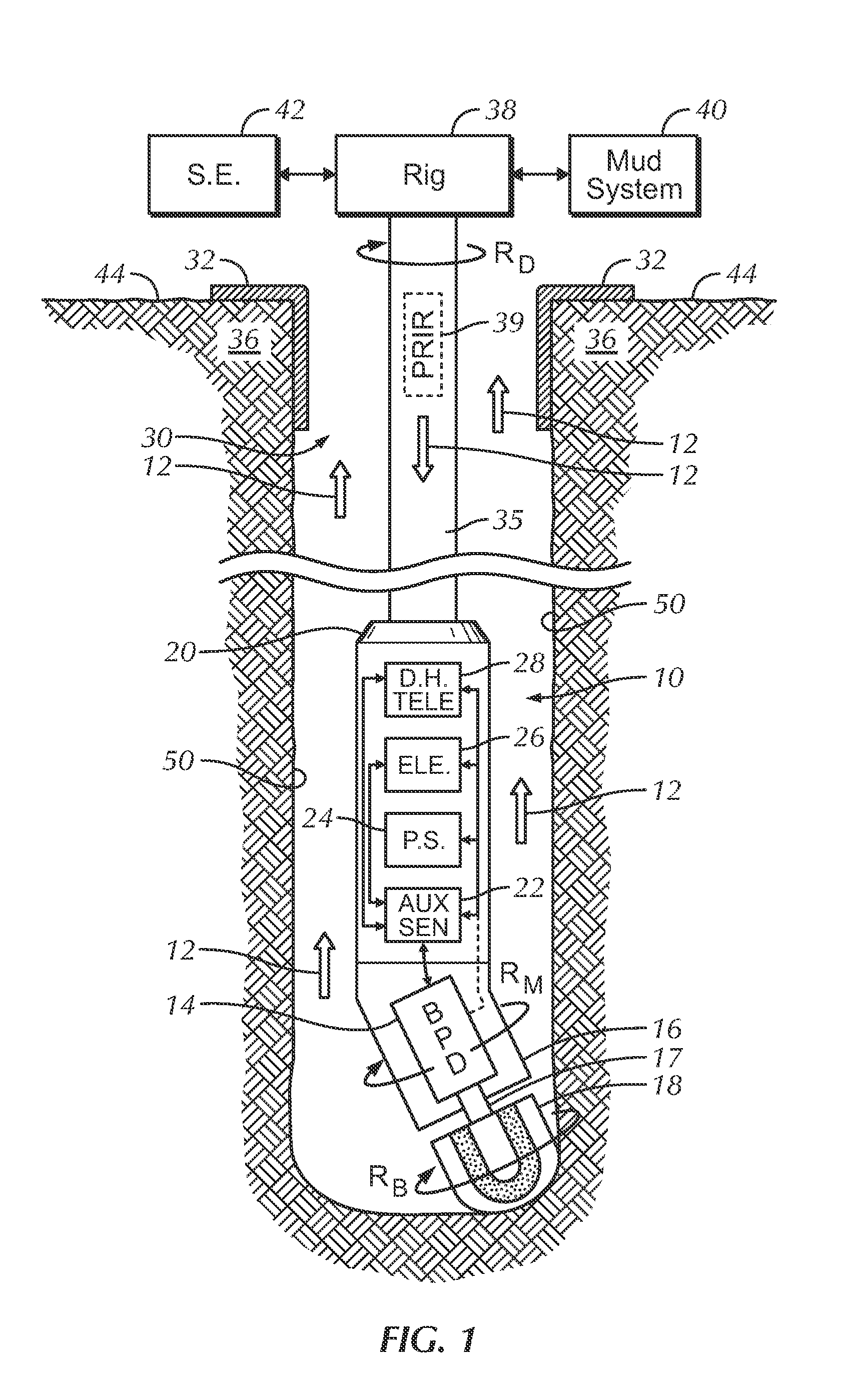
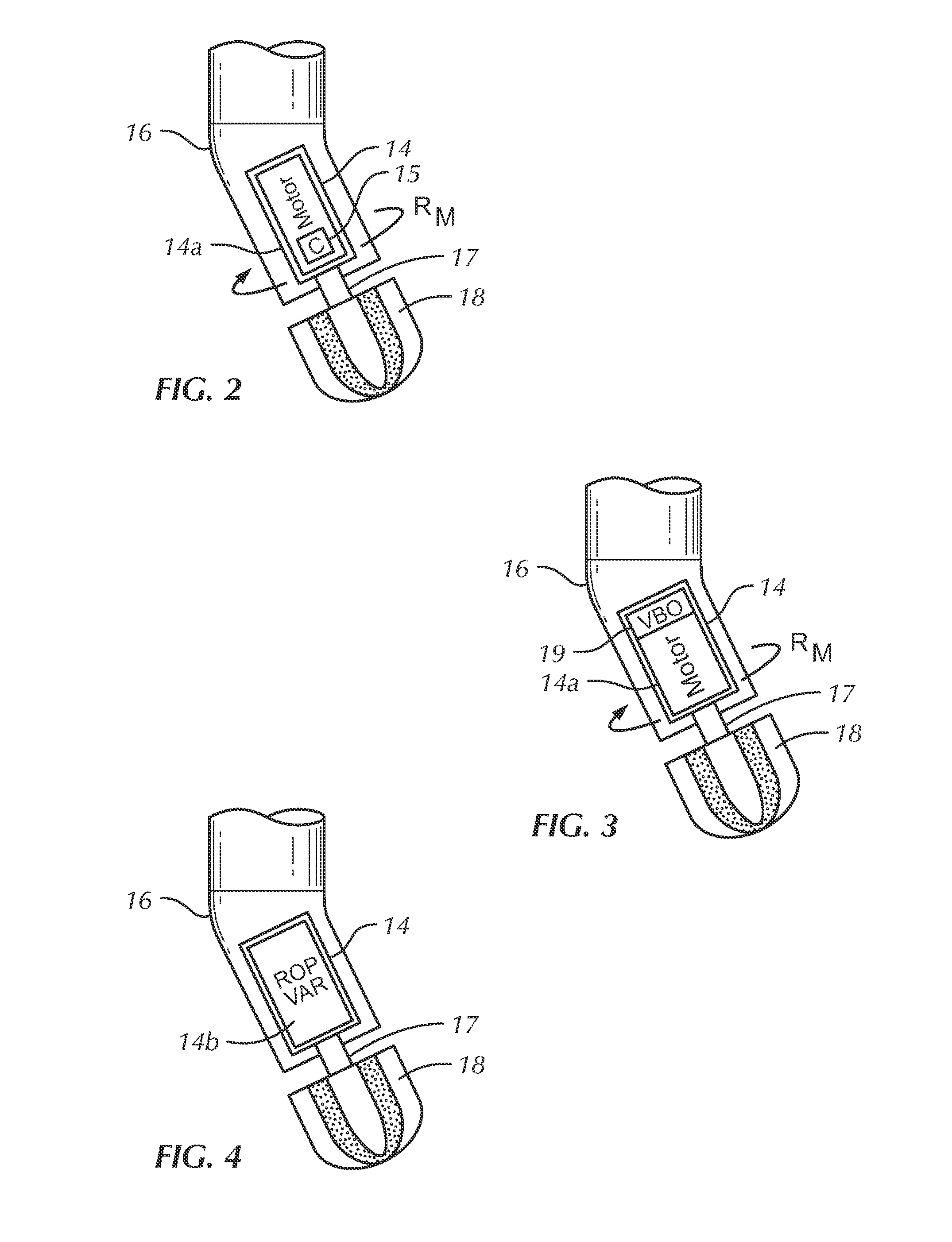
[0022]Directional drilling is obtained by periodically perturbing the action of the drill bit. For purposes of this disclosure “periodic variation” is defined as varying the drill bit rotation speed and / or rate of penetration (ROP) in a plurality of 360-degree drill string rotations or “cycles” at the same azimuthal arc in the plurality of rotations.

Hardware

[0023]Attention is directed to FIG. 1, which illustrates a borehole assembly (BHA) 10 suspended in a borehole 30 defined by a wall 50 and penetrating earth formation 36. The upper end of the BHA 10 is operationally connected to a lower end of a drill pipe 35 by means of a suitable connector 20. The upper end of the drill pipe 35 is operationally connected to a rotary drilling rig, which is well known in the art and represented conceptually at 38. Surface casing 32 extends from the borehole 30 to...


PUM


Abstract

Disclosed herein is a system for steering the direction of a borehole advanced by cutting action of a rotary drill bit by periodically varying action of a drill bit while continuously rotating a drill string to which the drill bit is operationally attached. The steering system can include a bit perturbation device cooperating with a bent housing subsection and operationally connected to the drill string and to the drill bit. Drill bit action can be varied by periodically varying the rotation speed and / or rate of penetration of the drill bit. Periodic drill bit action results in preferential cutting of material from a predetermined arc of the borehole wall which, in turn, results in borehole deviation. Action of the drill bit can be varied independently of the rotation rate of the drill string.

Description

[0001]This application is related to U.S. Pat. No. 7,766,098, and U.S. patent application Ser. No. 12 / 824,965, both entitled “Directional Drilling Control Using Modulated Bit Rotation,” which are incorporated herein by reference. This application is also a divisional of U.S. patent application Ser. No. 12 / 344,873, filed Dec. 29, 2008, entitled “Directional Drilling Control Using Periodic Perturbation of the Drill Bit,” which is also incorporated herein by reference.FIELD OF THE INVENTION[0002]This invention is related to the directional drilling of a well borehole. More particularly, the invention is related to steering the direction of a borehole advanced by a rotary drill bit by periodically perturbing the action of the drill bit during a revolution of the drill string to which the drill bit is operationally connected thereby allowing borehole trajectory to be controlled during continuous drill string rotation.BACKGROUND[0003]The complex trajectories and multi-target oil wells req...

Claims


Application Information

Patent Timeline
12 May 2011
Publication
US20110108327A1
IPC
E21B7/04; E21B7/08
CPC
E21B7/067; E21B44/005; E21B7/068
Inventors
FARLEY, STEVEN REID; LARRONDE, MICHAEL LOUIS