

Bone Distraction System
a distraction system and bone technology, applied in the field of bone distraction system, can solve the problems of obscuring the purpose of the device, affecting the accuracy of the device, so as to avoid the effect of obscuring the purpos
- Summary
- Abstract
- Description
- Claims
- Application Information
AI Technical Summary
Benefits of technology
Problems solved by technology
Method used
Image

Examples
Embodiment Construction
[0021]To provide an overall understanding of the invention, certain illustrative embodiments will now be described, including apparatuses, devices, systems and / or methods. However, it will be understood by one of ordinary skill in the art that the apparatuses, devices, systems and / or methods described herein may be adapted and modified as is appropriate for the application being addressed and that the systems and methods described herein may be employed in other suitable applications, and that such other additions and modifications will not depart from the scope hereof.
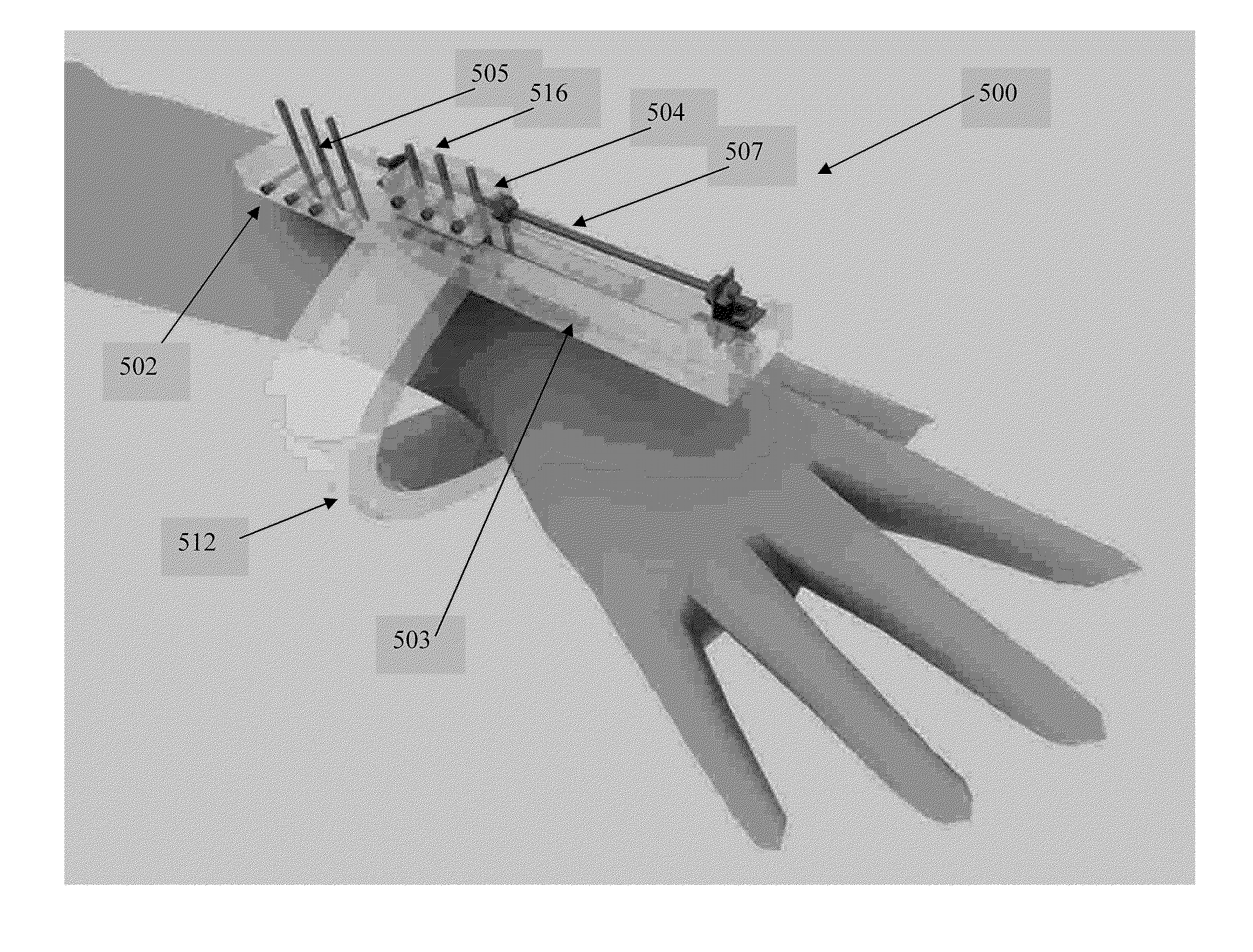
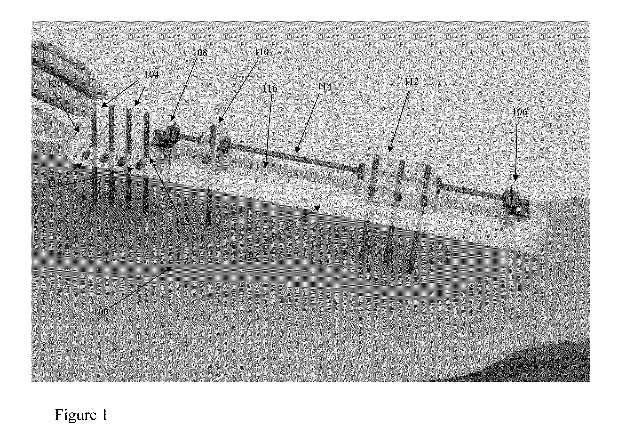
[0022]Distraction osteogenesis, also called callus callotasis, distraction, or osteodistraction is a surgical process used to reconstruct skeletal deformities and shorten or lengthen bones in the body. Distraction osteogenesis has the benefit of simultaneously increasing bone length and the volume of surrounding soft tissues. FIG. 1 illustrates one exemplary embodiment of the invention. In it, we see the overall syste...
PUM
 Abstract
Description
Claims
Application Information