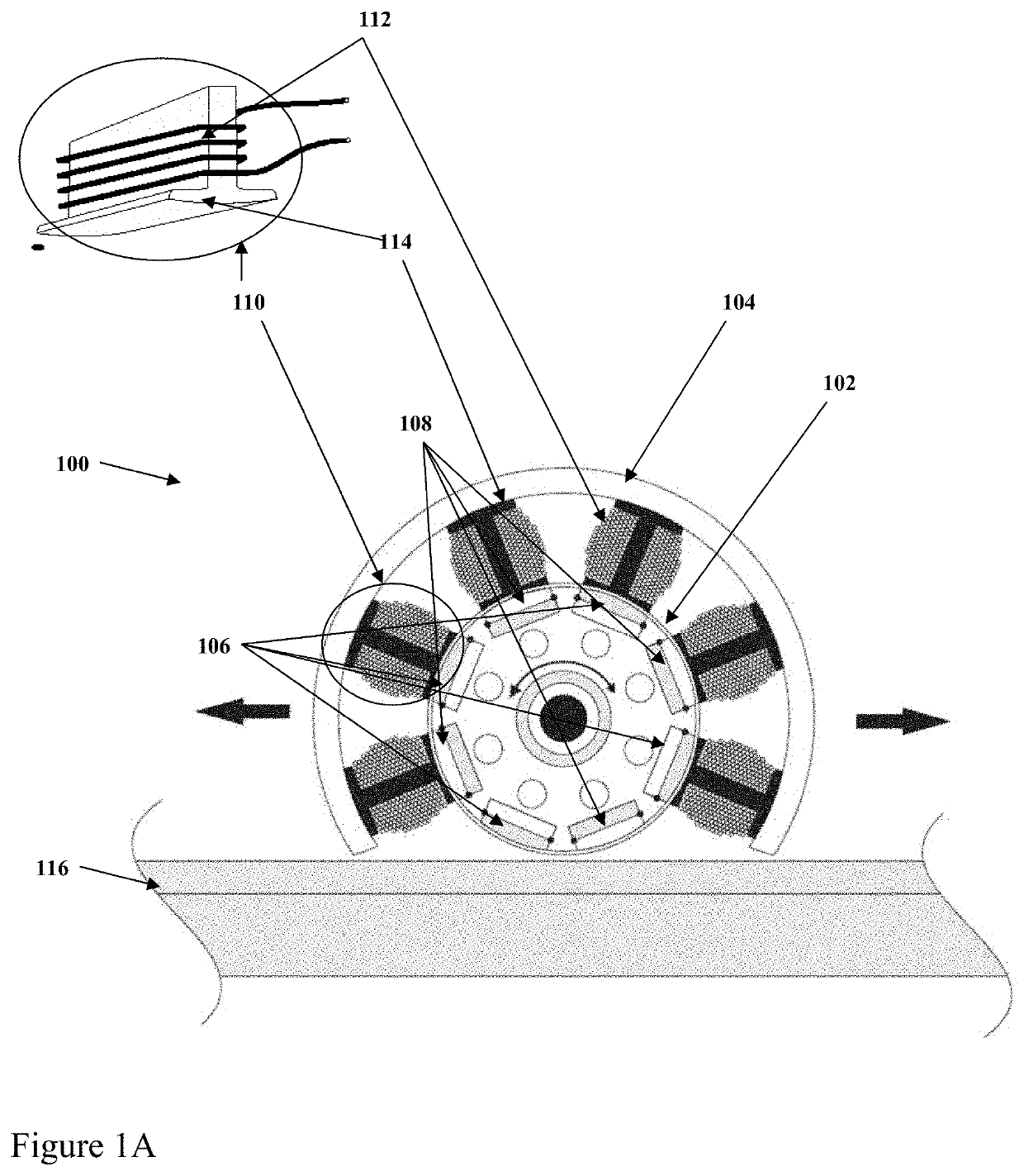
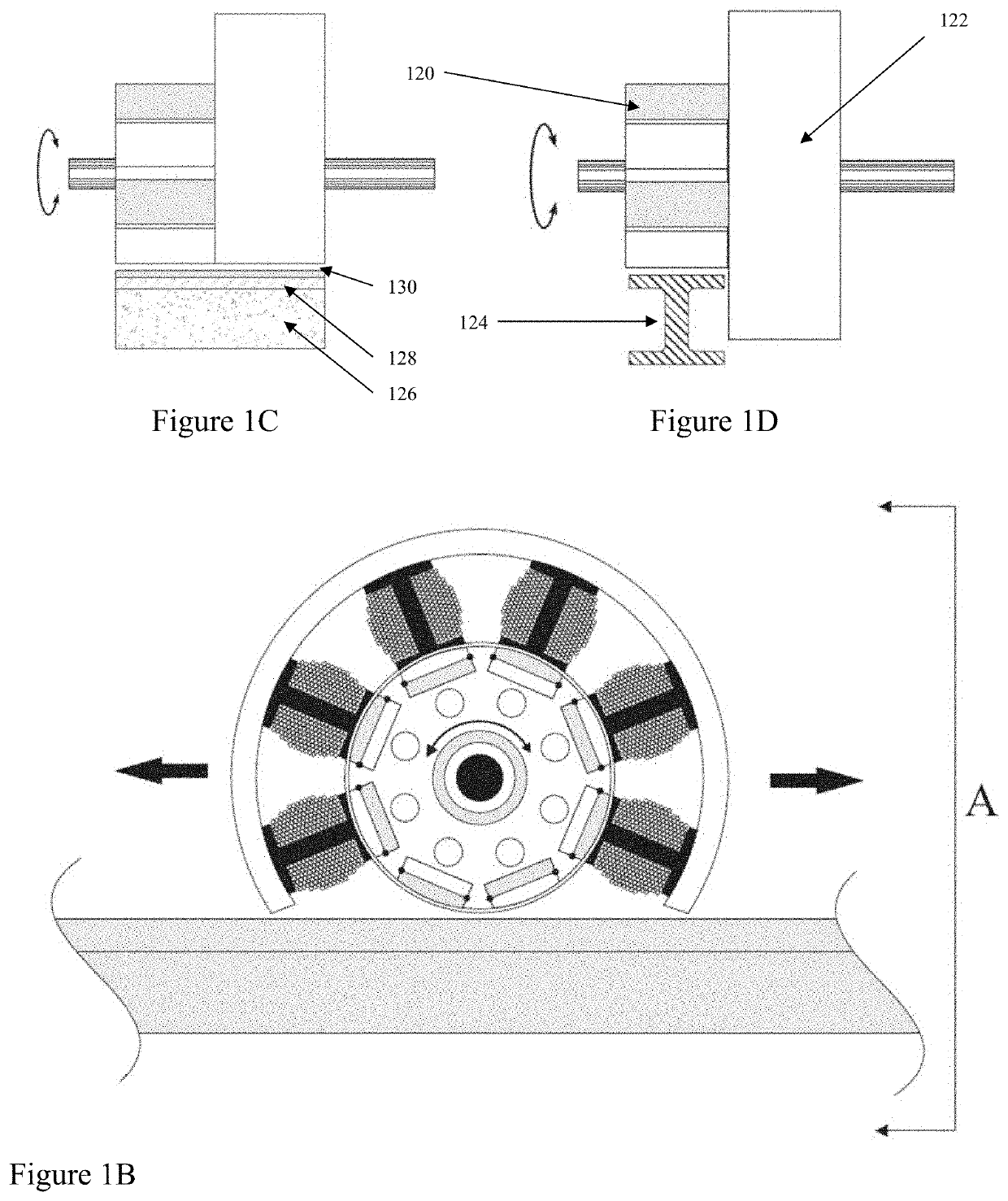
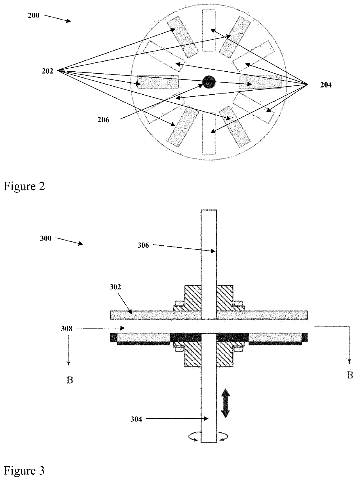
Dynamically Induced and Reactive Magnetic Hysteresis Applications and Methods

a dynamically induced and reactive technology, applied in the field of dynamically induced and reactive magnetic hysteresis, can solve the problems of limited advantages, and achieve the effect of avoiding obscuring the purpos

Inactive Publication Date: 2020-07-02
BERDUT ELBERTO
View PDF0 Cites 0 Cited by
  • Summary
  • Abstract
  • Description
  • Claims
  • Application Information

AI Technical Summary

Benefits of technology

[0006]This section is for the purpose of summarizing some aspects of the present invention and to briefly introduce some preferred embodiments. Simplifications or omissions may be made to avoid obscuring the purpose of the section. Such simplifications or omissions are not intended to limit the scope of the present invention.

Problems solved by technology

However, when using permanent magnets, the advantages have been limited by the need to have the permanent magnets create the transition via motion.

Method used


Image

  • Dynamically Induced and Reactive Magnetic Hysteresis Applications and Methods
  • Dynamically Induced and Reactive Magnetic Hysteresis Applications and Methods
  • Dynamically Induced and Reactive Magnetic Hysteresis Applications and Methods

Examples


Embodiment Construction

[0015]This section is for the purpose of summarizing some aspects of the present invention and to briefly introduce some preferred embodiments. Simplifications or omissions may be made to avoid obscuring the purpose of the section. Such simplifications or omissions are not intended to limit the scope of the present invention.

[0016]To provide an overall understanding of the invention, certain illustrative embodiments and examples will now be described. However, it will be understood by one of ordinary skill in the art that the same or equivalent functions and sequences may be accomplished by different embodiments that are also intended to be encompassed within the spirit and scope of the disclosure. The compositions, apparatuses, systems and / or methods described herein may be adapted and modified as is appropriate for the application being addressed and that those described herein may be employed in other suitable applications, and that such other additions and modifications will not...


PUM


Abstract

A dynamically induced magnetic hysteresis apparatus is described which allows efficient adjustable power coupling without direct mechanical attachment or linking. Adjustment of spatial and penetration gaps are adjusted to vary the ratio of rotation.

Description

CROSS-REFERENCE TO RELATED APPLICATIONS[0001]This application is a continuation of pending U.S. application. “Dynamically Induced and Reactive Magnetic Hysteresis Applications and Methods”, Ser. No. 15 / 062,087, filed on Mar. 5, 2016 the disclosure of which is incorporated herein by reference in its entirety.PATENTS CITED[0002]The following documents are incorporated by reference in their entirety, Wipf (U.S. Pat. No. 3,589,300), Cooper (U.S. Pat. No. 3,951,074), Post (U.S. Pat. No. 6,633,217), and Berdut (U.S. Pat. No. 5,615,618, U.S. patent application Ser. No. 12 / 838,955 and U.S. Pat. No. 8,487,504).TECHNICAL FIELD[0003]The present invention generally relates to the phenomena of dynamically induced and reactive magnetic hysteresis (DIMH), and in particular to its applications for levitation and power transfer within coupled mechanical systems in both vertical and horizontal applications.BACKGROUND[0004]The phenomena of power couplings and transfer using permanent and electromagnet...

Claims


Application Information

Patent Timeline
Patent Type & Authority Applications(United States)
IPC IPC(8): H02K49/10H02N15/00F16C32/04H02K7/10H02K7/00H02K49/06
CPCH02N15/00H02K7/003H02K49/10H02K7/10F16C32/04H02K49/065H02K1/276H02K1/02F16C32/0412F16C32/044F16C2326/10H02K1/2795
Inventor BERDUT, ELBERTO
Owner BERDUT ELBERTO
Why Eureka
Try Eureka