Screwstrip advance mechanism and feeder for a power screwdriver

Active Publication Date: 2011-09-29
SIMPSON STRONG TIE
View PDF8 Cites 24 Cited by
  • Summary
  • Abstract
  • Description
  • Claims
  • Application Information

AI Technical Summary

Benefits of technology

[0009]In a first of such functions, the components of the screw advance mechanism advance a screwstrip one position at a time to position each screw in the screwstrip in the target position. It may happen that portions of a screwstrip may be devoid of screws, such as for example at the beginning of a screwstrip. It is a further function of the components of the screw advance mechanism to allow the screwstrip to be easily advanced to a position where a screw is at or adjacent to the target position, while preventing the screwstrip from being pulled out in the opposite direction. It is another function of the components of the screw advance mechanism to lock a screwstrip in position while a screw is in the target position so that it remains in that location for driving by the power screwdriver.

Problems solved by technology

One problem which exists with conventional screw advance mechanisms for use with flexible screwstrips is the ability to accurately position the respective screws in the target position.
Occasionally the advance mechanism will under or overfeed the strip resulting in a misalignment of

Method used


Image

  • Screwstrip advance mechanism and feeder for a power screwdriver
  • Screwstrip advance mechanism and feeder for a power screwdriver
  • Screwstrip advance mechanism and feeder for a power screwdriver

Examples


Example

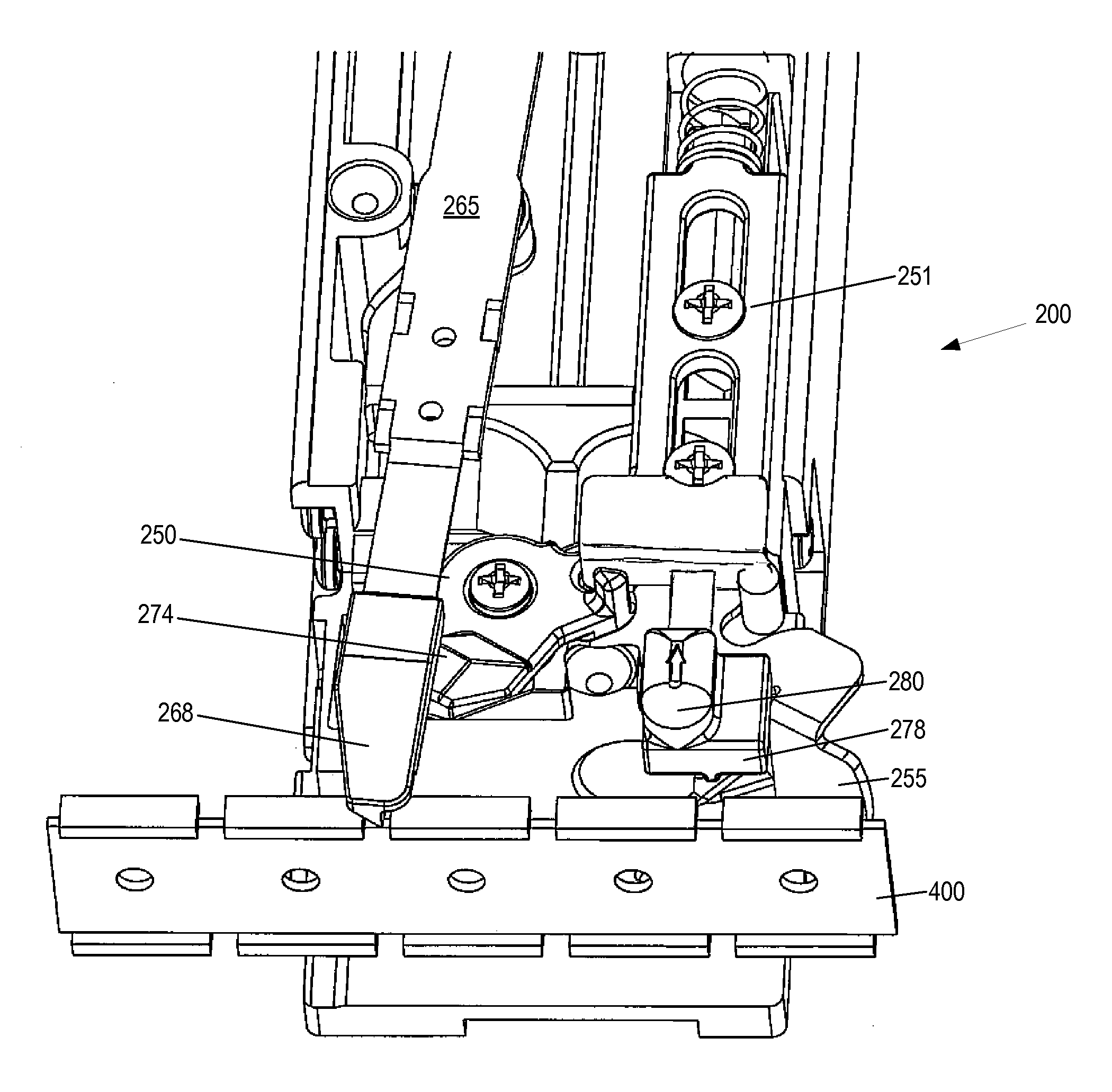
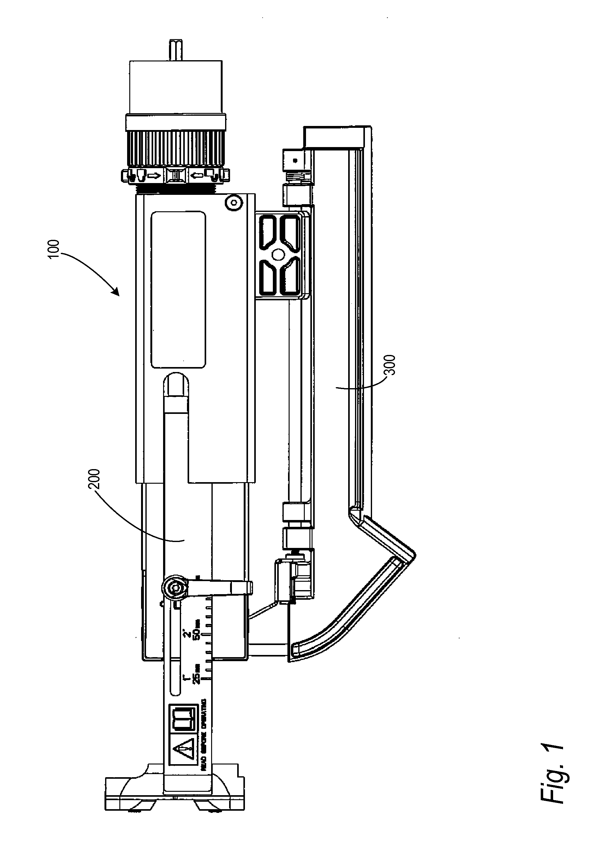
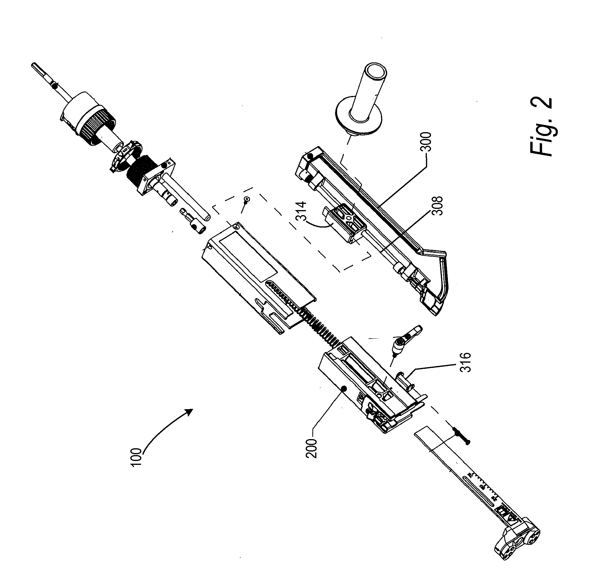
[0027]The present technology will now be described with reference to FIGS. 1 through 15 which in embodiments relate to a screw advance mechanism and screwstrip feeder mechanism for use in an autofeed power screwdriver. It is understood that the present technology may be embodied in many different forms and should not be construed as being limited to the embodiments set forth herein; rather these embodiments are provided so that this disclosure will be thorough and complete and will fully convey the technology to those skilled in the art. Indeed, the technology is intended to cover alternatives, modifications and equivalents of these embodiments, which are included within the scope and spirit of the technology as defined by the appended claims. Furthermore, in the following detailed description of the present technology, numerous specific details are set forth in order to provide a thorough understanding of the present technology. However, it will be clear to those of ordinary skill ...


PUM


Abstract

A power screwdriver is disclosed including a screw advance mechanism for advancing a screwstrip, and a hinged feed track for feeding the screwstrip to the screw advance mechanism.

Description

BACKGROUND[0001]1. Field[0002]The present technology relates to mechanisms for feeding and advancing a screwstrip with respect to a power screwdriver.[0003]2. Description of the Related Art[0004]Collated screwstrips are known in which the screws are connected to each other by a retaining strip of flexible plastic material. Such strips are taught, for example, by U.S. Pat. No. 4,167,229, entitled “Screw Strip and Method For Forming The Same,” and U.S. Patent Publication No. 2010 / 0032326, entitled “Screwstrip With Drive Slots Having Angled Sidewalls,” each of which is incorporated by reference herein in its entirety. Screws carried in such screwstrips are adapted to be successively and incrementally advanced to a position, referred to herein as the target position, in alignment with a bit of a reciprocating, rotating power screwdriver. Once a screw within the strip is properly aligned in the target position, the bit engages the screw and drives it into a workpiece. In the course of th...

Claims


Application Information

Patent Timeline
IPC IPC(8): B25B23/04B25B21/00
CPCB25B23/00B25B23/045
Inventor HALE, TROY
Owner SIMPSON STRONG TIE
Why Eureka
Try Eureka