Waste stream decontamination system

Active Publication Date: 2019-03-07
SANDYLAKES LTD
View PDF5 Cites 4 Cited by
  • Summary
  • Abstract
  • Description
  • Claims
  • Application Information

AI Technical Summary

Benefits of technology

[0097]In one embodiment, the contaminant trap and/or the one or more pollutant sorbent materials provided therein, are removable from the waste stream decontamination system for periodic cleaning of sequestered other pollutants therefrom. Preferably, the contaminant trap and/or one or more fresh or recycled pollutant sorbent materials may be easily returned and/or correctly repositioned within the reservoir for a subsequent round of treatment.
[0098]In certain embodiments, the contaminant trap itself is removably or immoveably fixed in position within the waste stream decontamination system, for example, through mounting or tethering means,

Problems solved by technology

Water remediation to remove (hydrocarbon based) pollutants from water waste is costly and often requires application of a range of biological, chemical and physical treatment processes, including expensive and time consuming chemical, microbial, enzymatic treatment while physical treatment processes include gravity separation, gas flotation, cyclonic separation, filtration and/or centrifuge separation techniques.
However, hydrocarbon contamination is particularly evident in sewage water from restaurants, commercial kitchens, fast food outlets, and the like, which typically comprise fats, oils and/or grease from food preparation, cooking and clean-up processes, as well as particulate solid food waste including burnt or charred food waste.
Many of the fats, oil and/or grease from food related sources have low melting points and thus tend to solidify and coagulate with solid waste materials at cold water temperatures, and can form large foul smelling and unsanitary masses of insoluble fats known as fatbergs.
Preventing and treating sewer damage caused by such fatbergs, as well as removing blockages to a mains sewage system places a significant cost burden on water/sewage authorities.
Existing grease traps are inefficient and compliance by the business owner with maintenance schedules is essential to avoiding excess contaminants entering the water network.
While environmental water standards relating to biological oxygen demand (BOD), total dissolved solids (TDS) and fats, oil and grease (FOG) content exist in relation to waste water, enforcement of these standards is a major issue and poor q

Method used


Image

  • Waste stream decontamination system
  • Waste stream decontamination system

Examples


Example

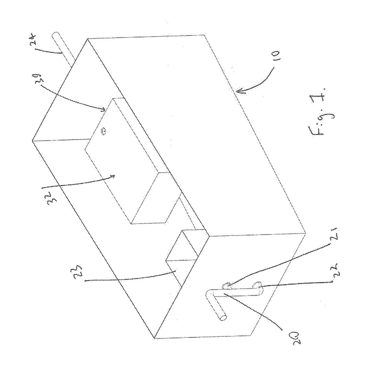
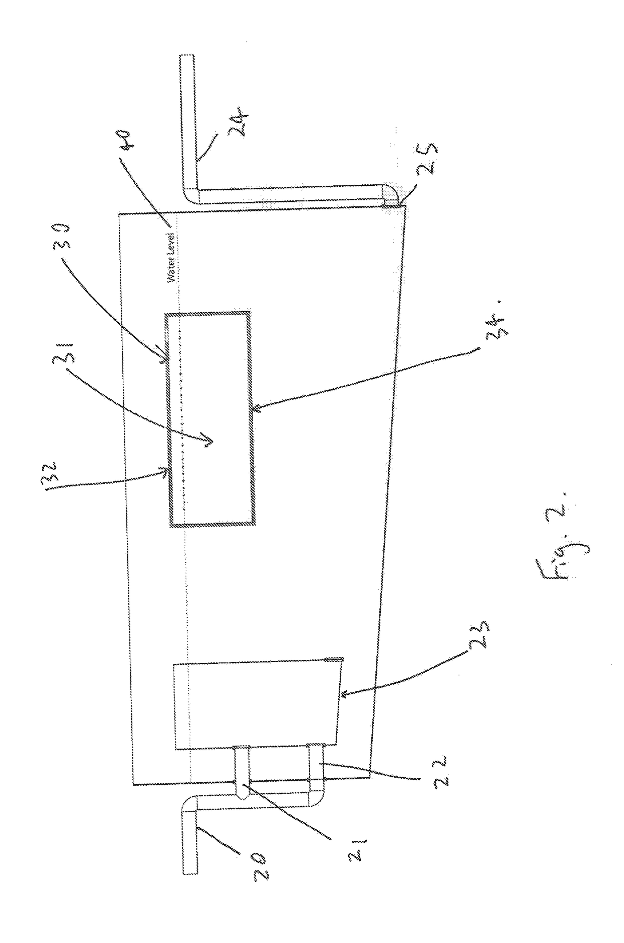
[0151]Referring now to the drawings and specifically FIGS. 1 and 2 inclusive and initially FIG. 1, which shows a front top right isometric view of a 3D representation of an assembled waste stream decontamination system of the invention, being in particular a grease trap, illustrated generally by reference number 1. The assembled grease trap 10 shown is generally rectangular in shape is comprises of four side walls A-D, consisting of front wall A, rear wall B and two side walls C and D respectively, bounded by bottom wall E and defining a grease trap reservoir for holding waste stream liquid of a predetermined volume. The bottom wall E of the grease trap 10 shown has a downward slope aware from the inlet side of the reservoir. This means that during use over time any non collected solid particulate flows towards the rear end of the reservoir assisting in a full clean out if needed. In use, a top wall or cover F is positioned on top of the four side walls A-D, effectively closing off ...


PUM


Abstract

The invention provides a method of decontaminating a waste stream liquid of solid particulate and one or more other pollutants, the method comprising the steps of: (i) removing solid particulate contaminant from the waste stream liquid by passing the waste stream liquid through at least one solids trap into a waste stream liquid holding reservoir whereby solid particulate is retained in the at least one solids trap; and (ii) removing one or more other pollutants from the waste stream liquid in the reservoir by contacting the waste stream liquid with at least one contaminant trap whereby the contaminant trap sequesters the one or more other pollutants within the contaminant trap.

Description

FIELD OF THE INVENTION[0001]The invention relates to a waste stream decontamination system, more particularly, a waste water treatment apparatus, and methods for using same, particularly, for the treatment of water and other waste streams to remove solids, and pollutants such as soluble and insoluble inorganic, organic and microbial pollutants, including hydrocarbon based pollutants, for example, fats, oil, and / or grease contaminants.BACKGROUND[0002]Water remediation to remove (hydrocarbon based) pollutants from water waste is costly and often requires application of a range of biological, chemical and physical treatment processes, including expensive and time consuming chemical, microbial, enzymatic treatment while physical treatment processes include gravity separation, gas flotation, cyclonic separation, filtration and / or centrifuge separation techniques.[0003]Sources of pollutants, including hydrocarbon based pollutants, in waste streams arise from hospitals, laboratories, and c...

Claims


Application Information

Patent Timeline
IPC IPC(8): C02F1/00C02F1/28C02F1/40E03F5/16
CPCC02F1/001C02F1/285C02F1/286C02F1/40E03F5/16C02F2307/08C02F1/28
Inventor SANDS, BRUCE KEITH
Owner SANDYLAKES LTD
Why Eureka
Try Eureka