Medical Imaging Apparatus and Method

a medical imaging and apparatus technology, applied in the field of medical imaging apparatus and method, can solve the problems of high distortion of image, requiring a great deal of experience to interpolate, and requiring great skill and experience to use such devices

Active Publication Date: 2011-09-29
HEADWATER PARTNERS I
View PDF7 Cites 35 Cited by
  • Summary
  • Abstract
  • Description
  • Claims
  • Application Information

AI Technical Summary

Benefits of technology

[0026]In yet further aspects of the method, the balloon has an expandable covering that promotes expan...

Problems solved by technology

Often, such an image is a highly distorted image, which requires a great deal of experie...

Method used


Image

  • Medical Imaging Apparatus and Method
  • Medical Imaging Apparatus and Method
  • Medical Imaging Apparatus and Method

Examples


Embodiment Construction

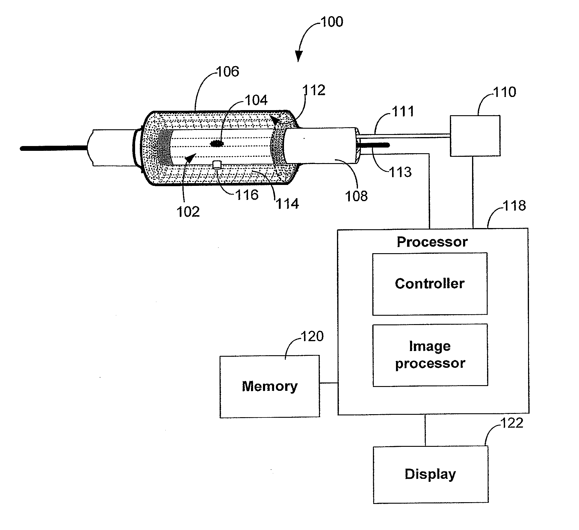
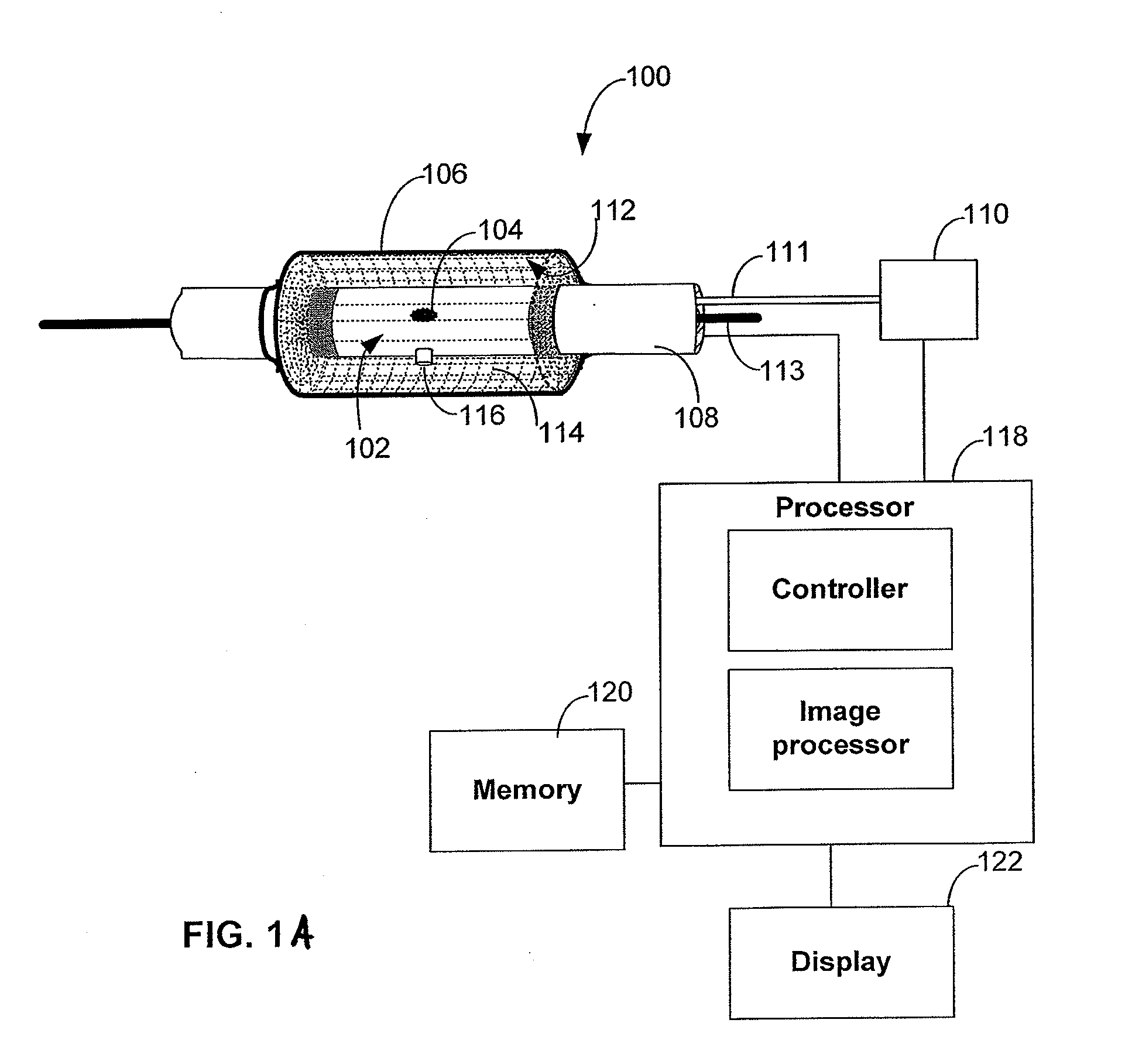
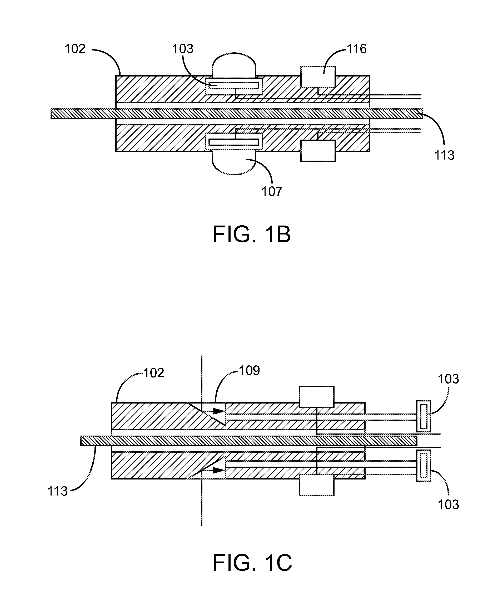
[0054]Embodiments of the invention are related to imaging methods and devices using a medical device such as a minimally invasive medical device, such as an arthroscopy device, a laparoscopy device, a cardiac catheter, or generally any medical device where remote imaging is used to guide the device. For example, a catheter can include an array of imaging sensors that are arranged in a pattern such that each imaging sensor has a distinct field of view, and accordingly image a portion of a body cavity, such as bodily lumen, that is distinct with respect to the other imaging sensors. The imaging sensors can be configured for use with energy transmitters used for imaging (e.g., piezoelectric transducer, LED), or alternatively incorporate the functionality of an energy transmitter (e.g., a piezoelectric transducer used to both transmit energy and receive reflected energy).

[0055]Each imaging sensor generally has a field of view that partially overlaps with at least one adjacent field of v...


PUM


Abstract

A medical device is used to image a body cavity using a plurality of axially and angularly spaced imaging sensors. Each i generates an image that is distinct from one another due to distinct fields of vision. Each image includes an overlapping zone with commonalities that are used to extrapolate a greater calibrated image.

Description

CROSS-REFERENCES TO RELATED APPLICATIONS[0001]This application claims the benefit of U.S. Provisional Application No. 61 / 317,794, filed on Mar. 26, 2010, and U.S. Provisional Application No. 61 / 317,797, filed on Mar. 26, 2010, and the entirety of each are incorporated by reference herein.BACKGROUND[0002]Minimum invasive surgery such as arthroscopy, balloon angioplasty, and vascular stenting, has revolutionized human medicine in the past few decades. In contrast to the traditional surgical method where large incisions are made and patients are examined and operated in an “open” manner, minimum invasive surgery only requires small incisions, surgery and diagnosis are carried out remotely with the aid of miniature cameras placed at the surgical sites. The ability to accurately image the surgical site is therefore crucial to the success of minimum invasive surgery and diagnosis and an improved imaging capability has the potential to further improve minimum invasive surgery and diagnosis...

Claims


Application Information

Patent Timeline
IPC IPC(8): A61B5/05
CPCA61B1/00177A61B5/7425A61B8/0883A61B8/12A61B8/4444A61B8/445A61B8/4477A61B8/5238A61B17/32002A61B2019/5278A61F2/2433A61F2/958A61M25/10A61M25/104A61B5/0086A61B5/6853A61B5/72A61B1/00181A61B2090/3782
Inventor RALEIGH, GREGORY G.
Owner HEADWATER PARTNERS I
Why Eureka
Try Eureka