OpenFlow COMMUNICATION SYSTEM AND OpenFlow COMMUNICATION METHOD

a communication system and communication method technology, applied in the field of openflow communication system and an openflow communication method, can solve the problems of increasing the number of openflow controllers b>10, increasing the facility cost and management cost, and achieving the effect of reducing the processing load of the openflow controller 10

Inactive Publication Date: 2011-10-27
NEC CORP
View PDF6 Cites 438 Cited by
  • Summary
  • Abstract
  • Description
  • Claims
  • Application Information

AI Technical Summary

Benefits of technology

[0036]Briefly describing the effect obtained by a typical one of the disclosed inventions, the OpenFlow communication system can be built in which processing load of the OpenFlow controller 10 can be reduced.
[0037]According to the present invention, the OpenFlow controller 10 transmits the route information of the packet 40 to the first OpenFlow switch 11 on the route, and route information is registered to the flow tables 23 of the OpenFlow switches 11 on the route, while relaying route information with the packet 40 along the route. By this configuration and operation, the number of times of the update instruction of the flow table 23 issued from the OpenFlow controller 10 to the OpenFlow switch 11 can reduced.

Problems solved by technology

However, such a scheme introduces the increase of a facility cost and a management cost in accompaniment with increase of the number of OpenFlow controllers 10, and complication of the OpenFlow controller 10 because a mechanism for synchronization establishment among plurality of OpenFlow controllers 10 becomes necessary separately.

Method used


Image

  • OpenFlow COMMUNICATION SYSTEM AND OpenFlow COMMUNICATION METHOD
  • OpenFlow COMMUNICATION SYSTEM AND OpenFlow COMMUNICATION METHOD
  • OpenFlow COMMUNICATION SYSTEM AND OpenFlow COMMUNICATION METHOD

Examples


first exemplary embodiment

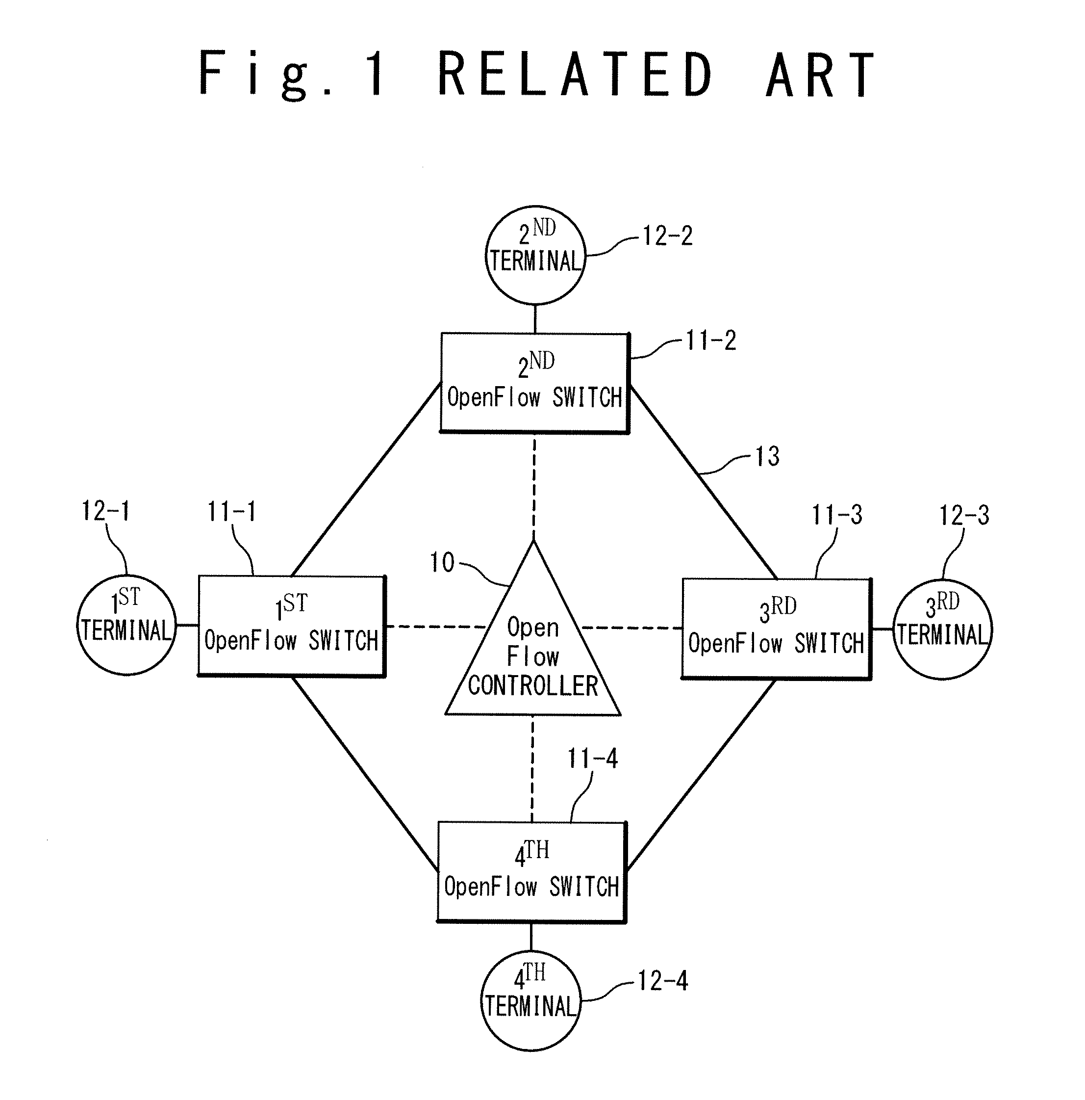
[0055]FIG. 6 is a block diagram showing a configuration of an OpenFlow controller 10 and an OpenFlow switch 11 in an OpenFlow communication system according to a first exemplary embodiment. It should be noted that in the present exemplary embodiment, the overall configuration of the OpenFlow communication system is similar to the above-mentioned configuration shown in FIG. 1. Also, in the current specification of OpenFlow, it is assumed that Ethernet (registered trademark) is used as a protocol for a data link layer and TCP / IP or UDP / IP is used as a protocol on a network layer and a transport layer. However, in the present exemplary embodiment, there is no constraint to the network protocols to be used. Also, in order to identify a plurality of OpenFlow switches 11 and terminals 12 disposed in the OpenFlow communication system, the component is identified by adding with a branch number, like a first OpenFlow switch 11-1, in the following description.

[0056]Referring to FIG. 6, an Ope...

second exemplary embodiment

[0098]A second exemplary embodiment of the present invention will be described below with reference to the drawings. The OpenFlow communication system according to the second exemplary embodiment executes the determination of whether the received packet 40 is the ordinary packet 41 or the encapsulated packet 50 by referring to the flow table 23 of the OpenFlow switch 11.

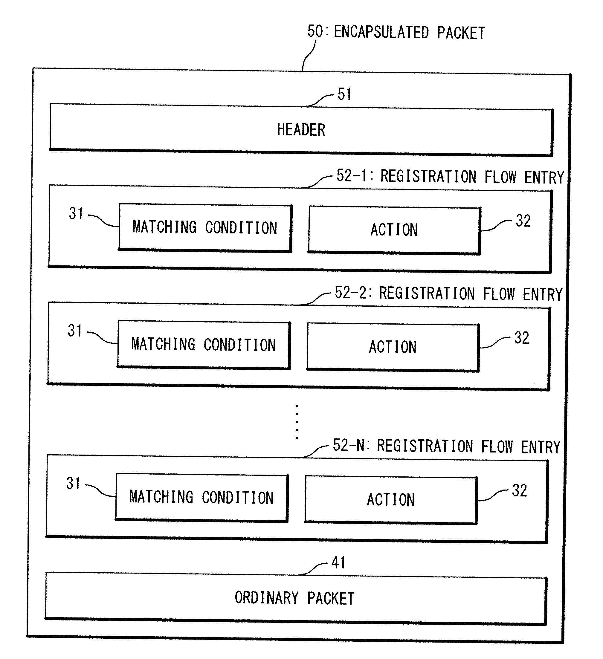
[0099]FIG. 14 is a block diagram showing the configuration of the flow entry 30 held by the flow table 23 of the OpenFlow switch 11 in the second exemplary embodiment. In the second exemplary embodiment, the flow entry 30 of FIG. 14 is registered on the flow table 23 of all the OpenFlow switches 11 in advance.

[0100]FIG. 15 is a flow chart showing the operation of the OpenFlow communication system in the second exemplary embodiment. The operation of the second exemplary embodiment is different from the operation of the first exemplary embodiment. A step of distinguishing the ordinary packet 41 and the encapsulated pac...


PUM


Abstract

An OpenFlow switch controls transmission and reception of a packet according to a flow entry. Each of the flow entries contains a matching condition showing a communication flow of the packet and an action showing processing on the packet. An OpenFlow controller generates a registration flow entry which is stored in a flow table of a specific OpenFlow switch arranged on a route of the communication flow. An encapsulated packet is generated by relating the registration flow entry and an ordinary packet. The specific OpenFlow switch extracts the registration flow entry from the encapsulated packet in response to the reception of the encapsulated packet to produce a new flow entry and executes the action shown in the new flow entry.

Description

CROSS-REFERENCE TO RELATED APPLICATION[0001]This is a continuation of International Application No. PCT / JP2010 / 052665, filed on Feb. 23, 2010.TECHNICAL FIELD[0002]The present invention is related to an OpenFlow communication system and an OpenFlow communication method.BACKGROUND ART[0003]Various techniques about a computer network are known (for example, refer to Patent Literatures 1 to 4). In Patent Literature 1, a technique of an IP flow table is described in which IP / MAC source address and destination address and an output physical port number are registered. In Patent Literature 2, a technique of a communication unit is described in which a route to another communication unit is determined based on stored routing information and also the routing information is updated according to update information. In Patent Literature 3, a technique of a packet relay unit is described in which a change of route information is received and corresponding information of a route table is register...

Claims


Application Information

Patent Timeline
Patent Type & Authority Applications(United States)
IPC IPC(8): H04L12/56H04L45/28H04L45/42
CPCH04L45/38H04L2212/0025H04L49/00H04L2212/00
Inventor ICHINO, KIYOHISA
Owner NEC CORP
Why Eureka
Try Eureka