Layer system for rotor/stator seal of a turbomachine and method for producing this type of layer system

a turbomachine and rotor seal technology, which is applied in the direction of liquid fuel engines, leakage prevention, motors, etc., can solve the problems of extremely limited running in, abrasive wear of guide vanes, and extremely hard covering layers, so as to achieve advantageous adjustment of hardness of running in layers

Inactive Publication Date: 2012-04-12
MTU AERO ENGINES GMBH
View PDF2 Cites 8 Cited by
  • Summary
  • Abstract
  • Description
  • Claims
  • Application Information

AI Technical Summary

Benefits of technology

[0015]According to a preferred enhancement of the layer system, the components are formed as a stator and a rotor of the turbomachine, the layer system being disposed on the rotor, and the stator being able to be run into the layer system. This reliably prevents a mechanical damaging of the rotor.
[0016]According to another preferred enhancement of the layer system, the first adhesive layer is formed as a metal adhesive layer and / or the second adhesive layer is formed as a metal adhesive layer, whereby advantageously, a reliable binding of the protective layer to the rotor is assured as well as a secure binding of the protective layer to the running-in layer. The operating reliability and the service life of the layer system are increased in this way.
[0017]According to another preferred enhancement of the layer system, the protective layer and the running-in layer are formed as ceramic layers. In this way, advantageously, a heat resistance and a corrosion resistance of the layer system are also assured at high operating temperatures of the turbomachine.

Problems solved by technology

It is a disadvantage in these systems that the covering layer is extremely hard and only an extremely limited running in would be possible without massive damage to the vane or the coating.
In fact, if a rotor protection were to be assured, the guide vanes would be abrasively worn, however.

Method used


Image

  • Layer system for rotor/stator seal of a turbomachine and method for producing this type of layer system
  • Layer system for rotor/stator seal of a turbomachine and method for producing this type of layer system
  • Layer system for rotor/stator seal of a turbomachine and method for producing this type of layer system

Examples


Embodiment Construction

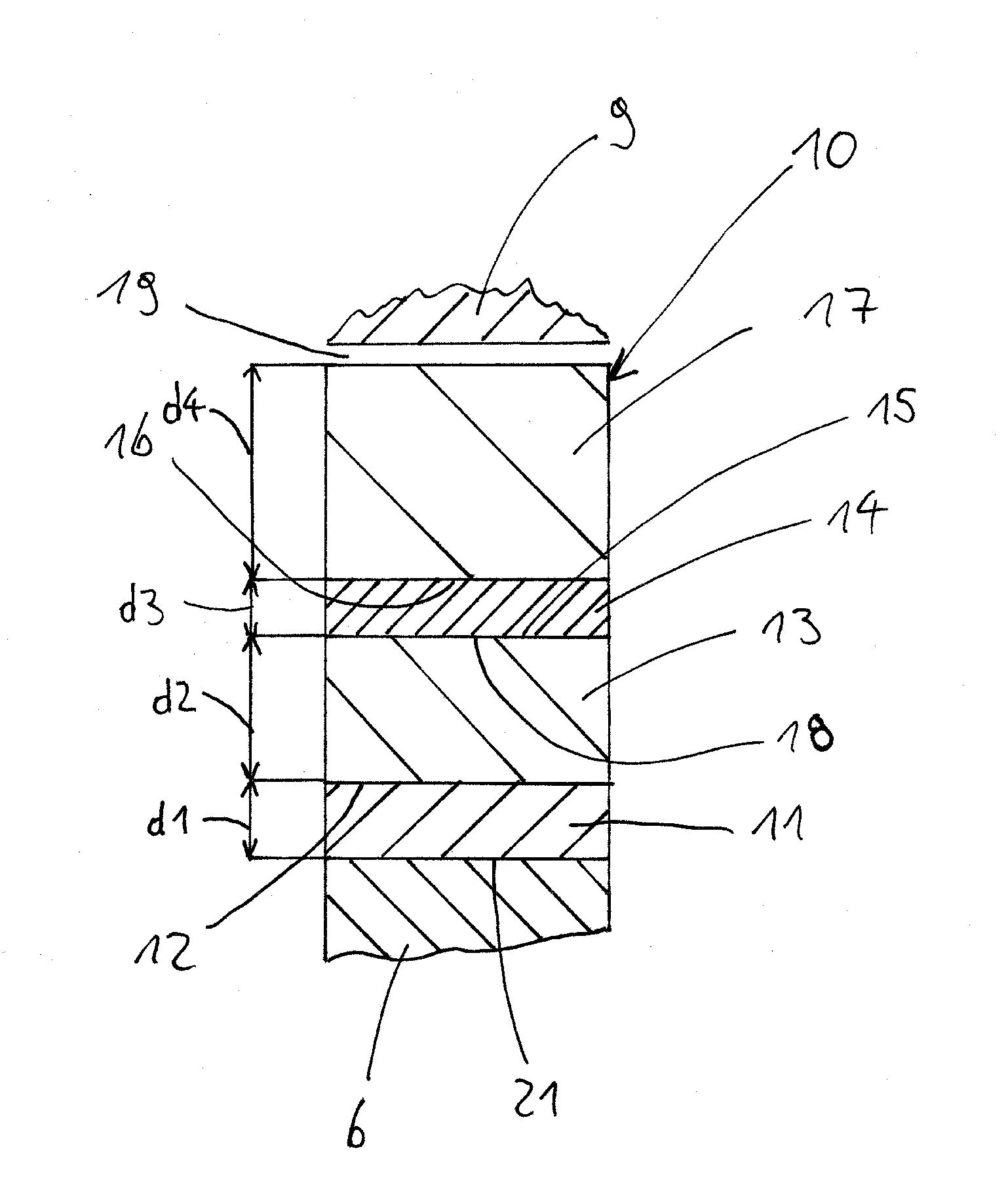
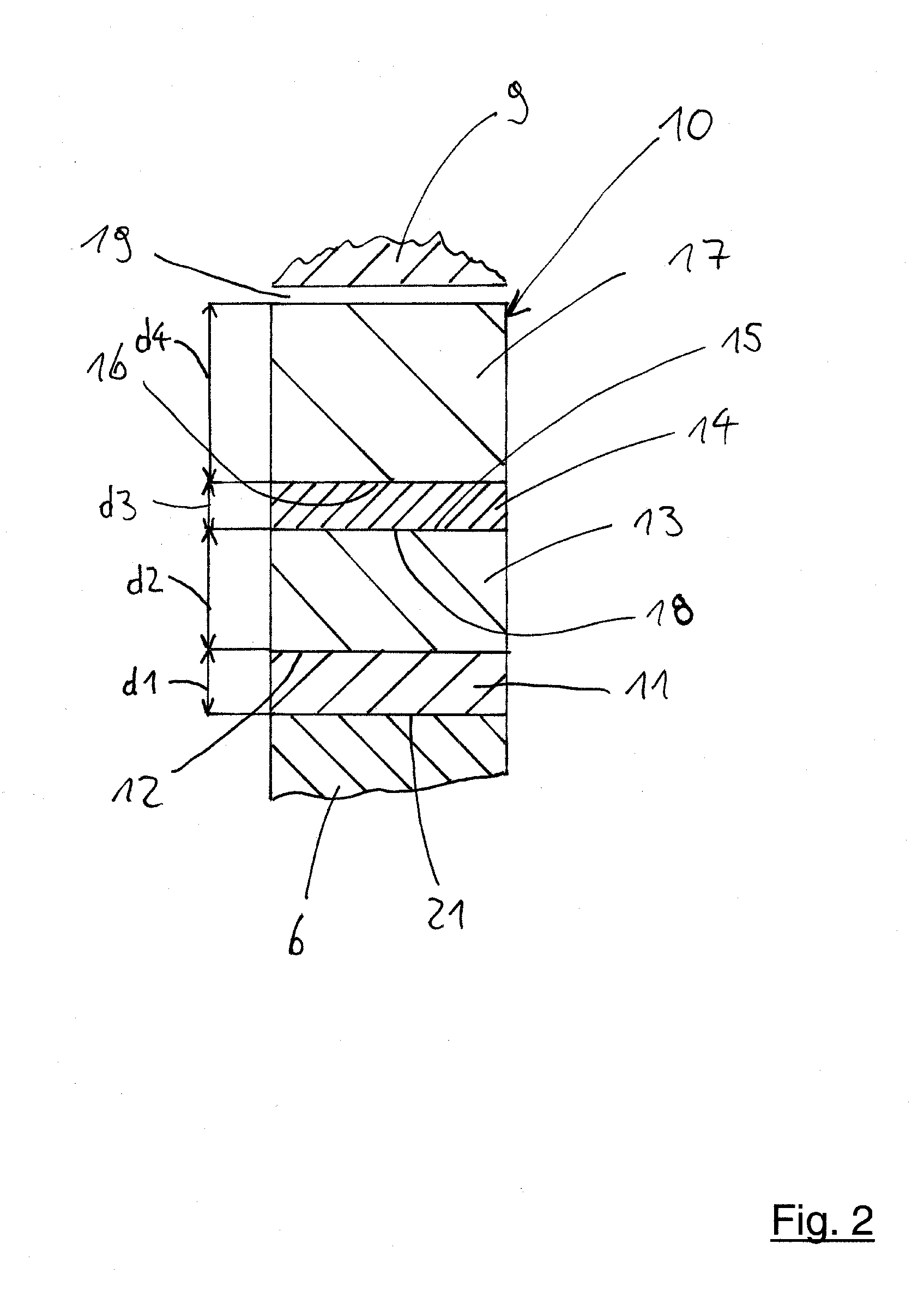
[0024]In the figures of the drawing, identical elements and features, as well as those that are functionally identical, are provided with the same reference numbers, unless otherwise stated.

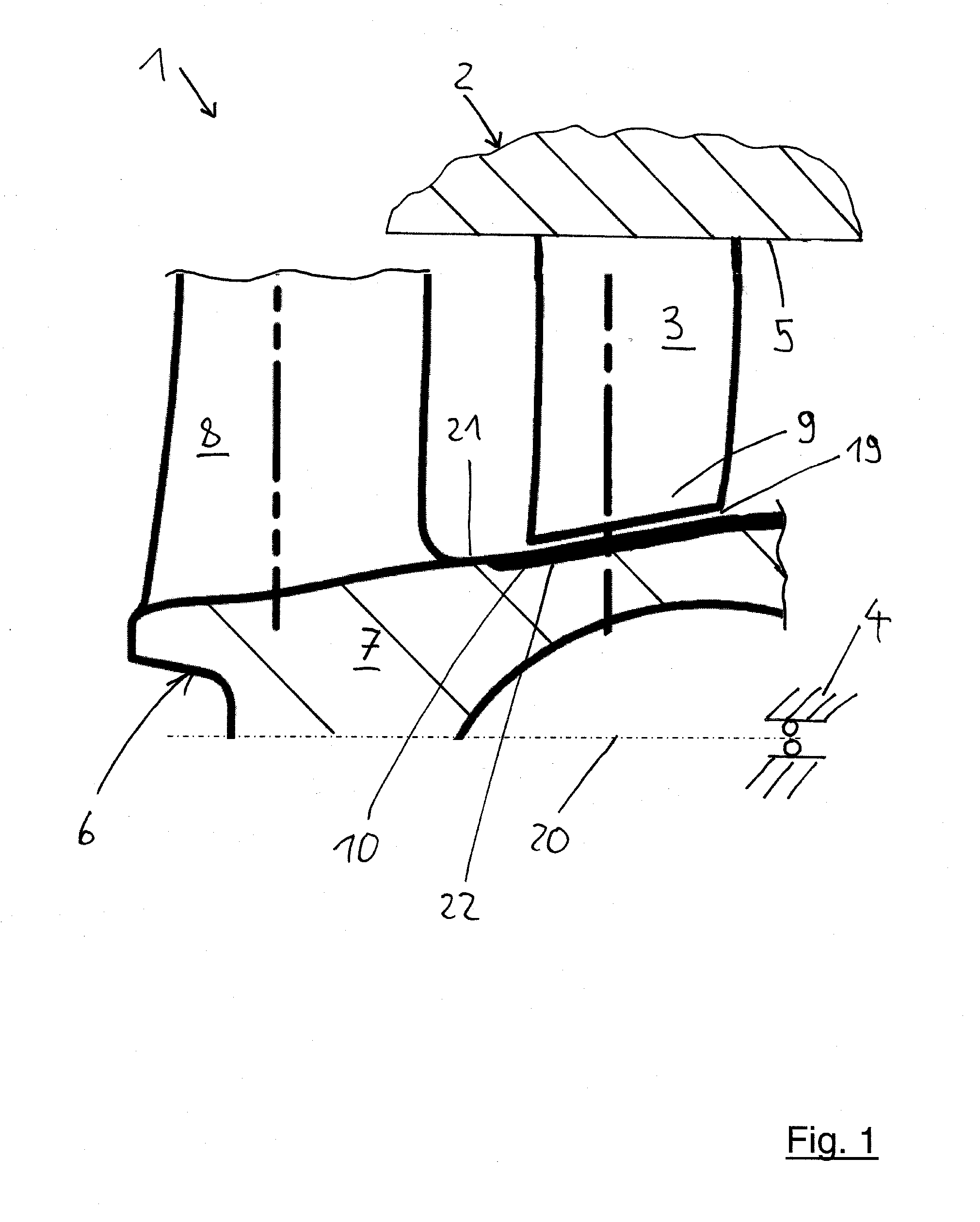
[0025]In a partial sectional view, FIG. 1 illustrates a turbomachine 1, in particular a compressor 1. The turbomachine 1, for example, has a first component 6, which is preferably designed as a rotor 6 of the turbomachine 1, and a second component 2, which is designed, for example, as a stator 2 of the turbomachine 1. The components 2, 6 are movable relative to one another. Preferably, the rotor 6 can be rotated around a central axis 20 in a housing 4, in particular in a compressor housing 4 of the turbomachine 1. For example, the rotor 6 has a hub 7 and compressor blades operatively connected to the hub 7; of these only one compressor blade 8 is shown. The compressor blades are preferably disposed around a circumference of the hub, uniformly distanced from one another. The rotor 6, for example, ...


PUM

PropertyMeasurementUnit
thickness d2aaaaaaaaaa
adhesiveaaaaaaaaaa
porosityaaaaaaaaaa

Abstract

The present invention creates a layer system for the rotor / stator seal of a turbomachine, in particular a compressor, which is disposed between components of the turbomachine and can be run in with a movement of the components relative to one another, in such a way that at least one of the components is run into the layer system, having: a first adhesive layer disposed on at least one of the components; a protective layer disposed on the first adhesive layer; a second adhesive layer disposed on the protective layer; and a running-in layer, which is formed softer than the protective layer and which is disposed on the second adhesive layer. The present invention further provides a method for producing a layer system for the rotor / stator seal of a turbomachine, as well as a turbomachine.

Description

CROSS REFERENCE TO RELATED APPLICATION[0001]N / ABACKGROUND OF THE INVENTION[0002]The present invention relates to a layer system for the rotor / stator seal of a turbomachine, in particular a compressor, a method for producing this type of layer system, and a turbomachine, in particular a compressor having this type of layer system.[0003]Although it is applicable to any turbomachine, the present invention as well as its underlying problem will be explained in more detail with reference to a compressor.[0004]In running in shroud-free compressor guide vanes of a stator into a rotor of a turbomachine, the requirements that are to be fulfilled include protecting the rotor from damage and simultaneously enabling a running in of the compressor guide vanes into the rotor that is as deep as possible in order to assure an optimized running gap between the tips of the compressor guide vanes and the rotor. This must not lead to damage of the compressor guide vanes, however.[0005]DE 102 25 532 C1 ...

Claims


Application Information

Patent Timeline
Patent Type & Authority Applications(United States)
IPC IPC(8): F01D11/00C09J5/10
CPCF01D5/288F01D11/08F05D2230/90F05B2230/90F01D11/122F01D11/001F05D2300/514F05D2230/311F05D2300/2118F05D2300/2112
Inventor METSCHER, MARTIN
Owner MTU AERO ENGINES GMBH
Why Eureka
Try Eureka