Monitoring system

a monitoring system and system technology, applied in the field of monitoring systems, can solve problems such as difficult to elucidate specifications (e.g. informational requirements), insufficiently integrated support capability, and design of health management systems for legacy platforms or particularly complex new platforms

Active Publication Date: 2012-05-24
BAE SYSTEMS PLC
View PDF12 Cites 26 Cited by
  • Summary
  • Abstract
  • Description
  • Claims
  • Application Information

AI Technical Summary

Benefits of technology

[0080]By providing for design of the platform in a modular way, the addition of further primary sub-systems to the platform can readily be accommodated. Furthermore, a secondary sub-system for monitoring a complex platform, comprising many primary sub-systems, can be designed easily using the method.

Problems solved by technology

The result can be an inadequately integrated support capability.
However, designing a health management system for a legacy platform, or for a particularly complex new platform, can be problematic.
For example, it can be difficult to elucidate the specifications (e.g. informational requirements) for a health management system, in terms of information that should or must be obtained, processed and output by the health management system so as to fulfil the needs of operators, service personnel and other users of the system.
Furthermore, without a clear understanding of these information specifications, it becomes difficult to produce a design for a health management system, in terms of the sub-systems that must or should be monitored, the sensors to be used for such monitoring, and the data processing to convert the output of such sensors into the desired information.

Method used


Image

  • Monitoring system
  • Monitoring system
  • Monitoring system

Examples


first embodiment

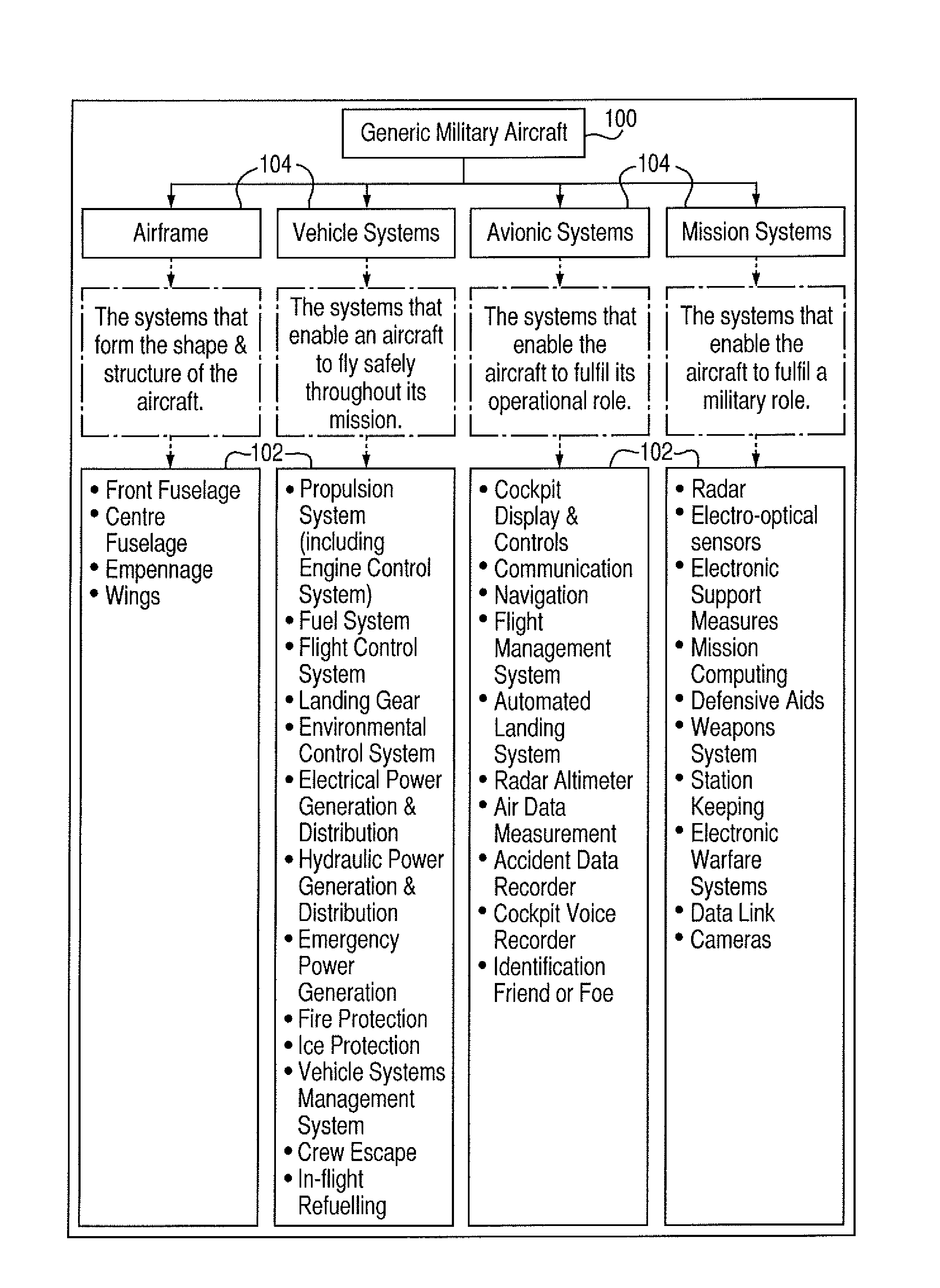
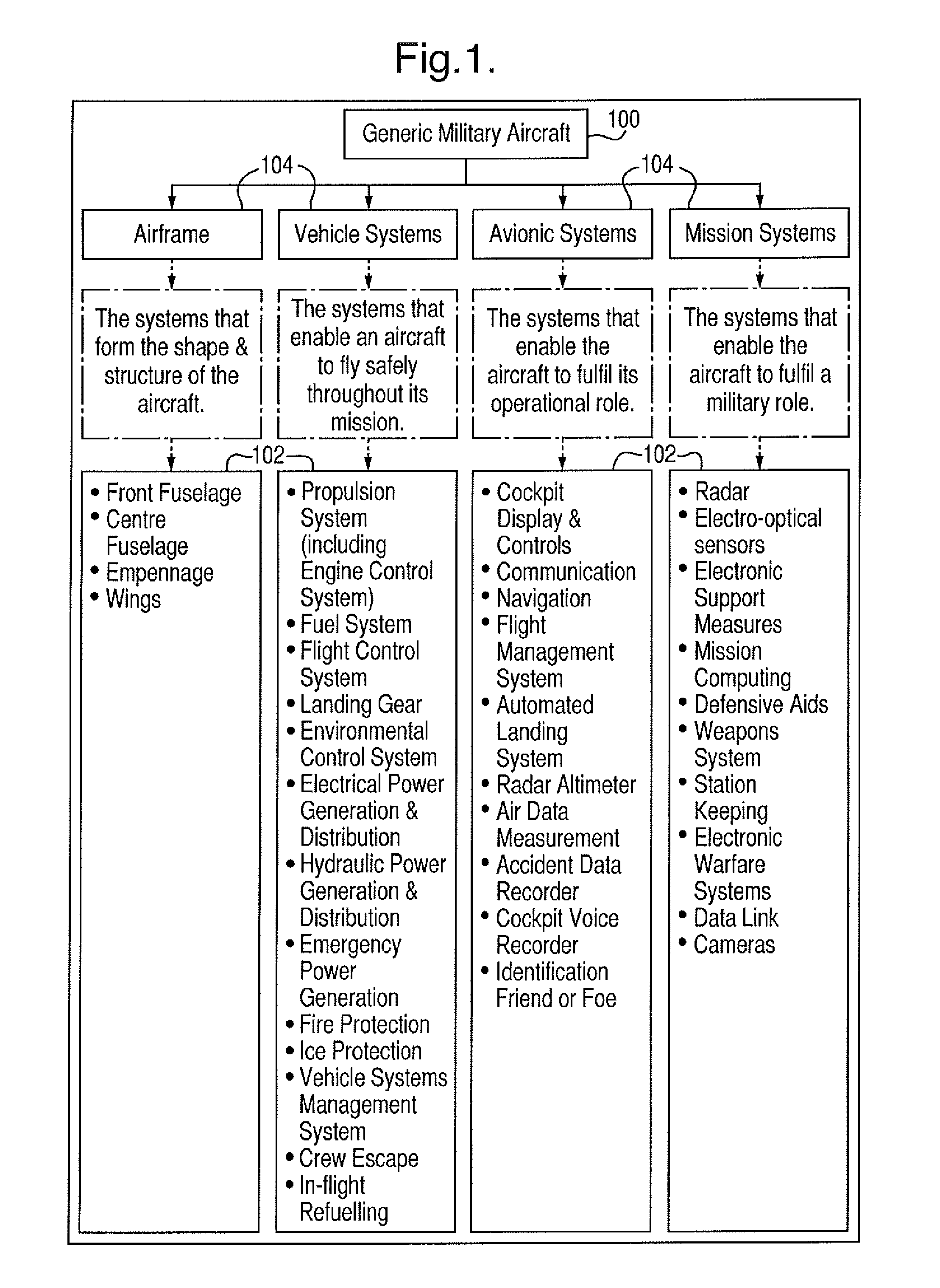
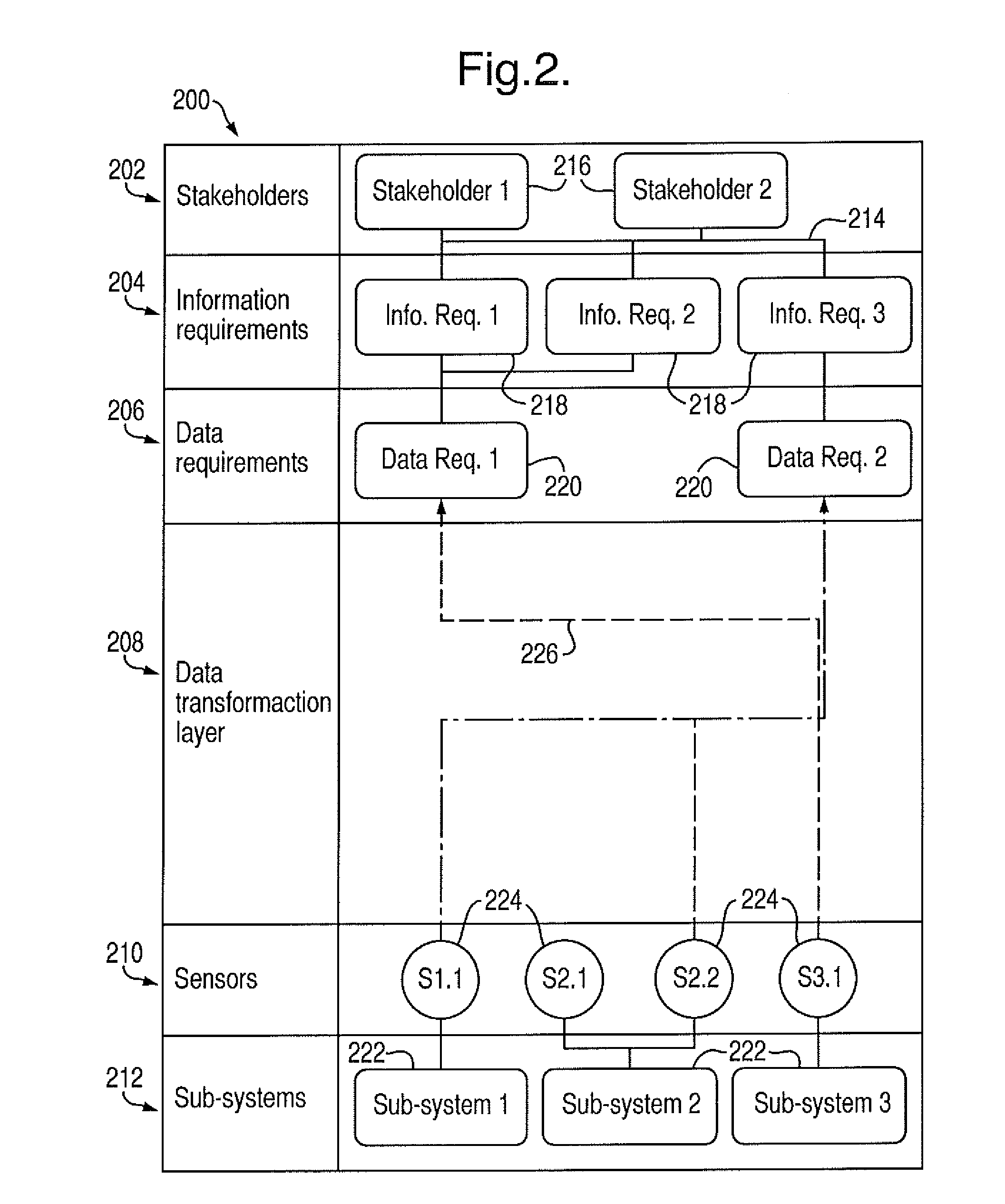
[0100]FIG. 2 shows, schematically, a secondary sub-system of a platform, in the form of a health management system 200. The health management system 200 is configured to monitor the health of a platform comprising a plurality of sub-systems, for example of the type shown generically in FIG. 1.

[0101]In FIG. 2, the health management system 200 is represented as a plurality of layers arranged in a hierarchical manner. Each layer represents an information type or procedure that can be populated when designing the health management system 200. In other words, each layer specifies the essential information required for the design of the health management system 200 in a logical and generic (i.e. not platform-specific) way. Therefore, FIG. 2 can be considered to represent schematically both the structure of the health management system 200 itself, and a graphical user interface of a design tool used to design a health management system 200, as will be explained in more detail below.

[0102]T...

second embodiment

[0143]FIG. 5 shows, schematically, a secondary sub-system for monitoring the condition of a platform, in the form of a health management system 230. As for FIG. 2, FIG. 5 represents the structure of the health management system 230, and again can also be considered as a schematic representation of a graphical user interface of a design tool used to design the health management system 230.

[0144]The health management system 230 of the second embodiment has the same hierarchical structure as the first embodiment shown in FIG. 2, and like reference signs are used in FIG. 5 to denote like features.

[0145]The health management system 230 of FIG. 5 differs from the first embodiment shown in FIG. 2 in that the information requirements layer 204 and the data requirements layer 206 can each contain a hierarchical structure of requirement blocks 218, 220.

[0146]In the FIG. 5 example, the information requirements layer 204 includes an information requirement block 218 denoted Info. Req. 3, which ...

third embodiment

[0156]FIG. 6 shows, schematically, part of a secondary sub-system for monitoring the condition of a platform, in the form of a health management system 240. In this embodiment, as in previous embodiments, the health management system 240 comprises a hierarchical structure of stakeholders, information requirements, data requirements, data transformation, sensors and sub-systems layers (such as shown in FIGS. 2 and 5). Only the stakeholders layer 202 and the information requirements layers 204 are shown in FIG. 6.

[0157]This third embodiment includes an additional information use layer 242, which lies outside the hierarchical structure and parallel to the data requirements layer, so as not to disrupt the top-to-bottom flow of data through the hierarchical layer structure of the health management system 240.

[0158]The use layer 242 comprises a plurality of use blocks 244, each use block 244 being connected to an information requirement block 218 in the information requirements layer 204....


PUM


Abstract

A method for designing a secondary sub-system for monitoring the condition of a platform is disclosed. The platform can include one or more primary sub-systems. The method can include identifying stakeholders of the platform, capturing information requirements of the stakeholders, determining data requirements corresponding to the information requirements, defining a sensor array comprising sensors suitable for providing output signals relating to condition characteristics of the one or more primary sub-systems, and defining procedures for converting the output signals from the sensor array to the data requirements, thereby to fulfil the information requirements of the stakeholders. The method can be implemented using a design tool having a graphical user interface with a hierarchical layer structure.

Description

FIELD OF THE INVENTION[0001]A monitoring system is disclosed, such as a sub-system for monitoring a primary system. In one example, a health management system is disclosed for monitoring a plurality of sub-systems of a platform, such as a vehicle platform (for example an aircraft), and a method for designing such a health management system is also disclosed.BACKGROUND TO THE INVENTION[0002]Complex, highly-integrated systems have become commonplace in many areas of technology. Examples of highly-integrated systems include mobile vehicles such as modern fast jet fighters and civilian airliners, unmanned aerial vehicles, industrial structures such as power plants, chemical plants and off-shore oil and gas platforms, and large-scale experimental apparatus such as particle accelerators and fusion reactors. Each of these systems can be considered as a platform that hosts a large number of sub-systems, each sub-system being arranged to perform a specific function of the overall system and ...

Claims


Application Information

Patent Timeline
Patent Type & Authority Applications(United States)
IPC IPC(8): G06F17/50
CPCG05B17/02G06F8/34G05B2219/37027
Inventor KHELLA, MANDEEP SINGH
Owner BAE SYSTEMS PLC
Why Eureka
Try Eureka