Building system with multi-function insulation barrier

a multi-functional, building technology, applied in the direction of walls, ceilings, building repairs, etc., can solve the problems of reducing the aesthetic appeal of the final wall, more serious situation, and difficulty

Inactive Publication Date: 2012-07-12
JAMES HARDIE TECH LTD
View PDF7 Cites 19 Cited by
  • Summary
  • Abstract
  • Description
  • Claims
  • Application Information

AI Technical Summary

Benefits of technology

[0054]In some embodiments, the body of the insulating element is a homogenous construction. In other embodiments, the body of the insulating element is a multi-layered construction. In layered embodiments of the insulating element the body at least one layer is formed of a material having at least one different physical property relative to the material used to form one or more of the other layer or layers. The use of multi-layered insulating elements advantageously enables an insulating element to be constructed so as to be suitable for use with particular cladding and framing materials, to account for irregularities in the cladding and / or framing materials, to account for expected environmental conditions and / or to suit the method of construction used for erecting the building section.

Problems solved by technology

However, any discussion of the prior art throughout the specification should in no way be considered as an admission that such prior art is widely known or forms part of common general knowledge in the field.
One difficulty which arises in constructing some cladding systems, is the need to correctly align the mating surfaces of adjacent cladding panels on the frame, and to maintain this alignment after the erection process has been completed.
However, using popular soft foam thermal insulating strips for example, it is often difficult to achieve such a flat surface at the adjoining or abutting edges of adjacent panels, which reduces the aesthetic appeal provided by the final wall.
This difficulty arises, at least in part, due to the physical properties of these soft foam insulating strips and / or irregularities in the frame.
Such misalignment of adjacent cladding panels can give rise to a more serious situation where the building section is a floor of the building.
In particular, such misalignment of adjacent panels or floor boards can give rise to undesirable unevenness in flooring.
While rigid polystyrene foam alternatives used for walls and high density rubber sheets used for floors reduce this problem to some extent, they are slow to install and awkward to transport.
Another issue which arises with the use of soft foam strips is that, when either hand or gun nailing the cladding panels to the frame, the nails are often over driven such that an indentation is formed in the cladding panel and the head of the nail sits beneath the surface of the panel, again reducing the aesthetic appeal provided by the wall.

Method used


Image

  • Building system with multi-function insulation barrier
  • Building system with multi-function insulation barrier
  • Building system with multi-function insulation barrier

Examples


Embodiment Construction

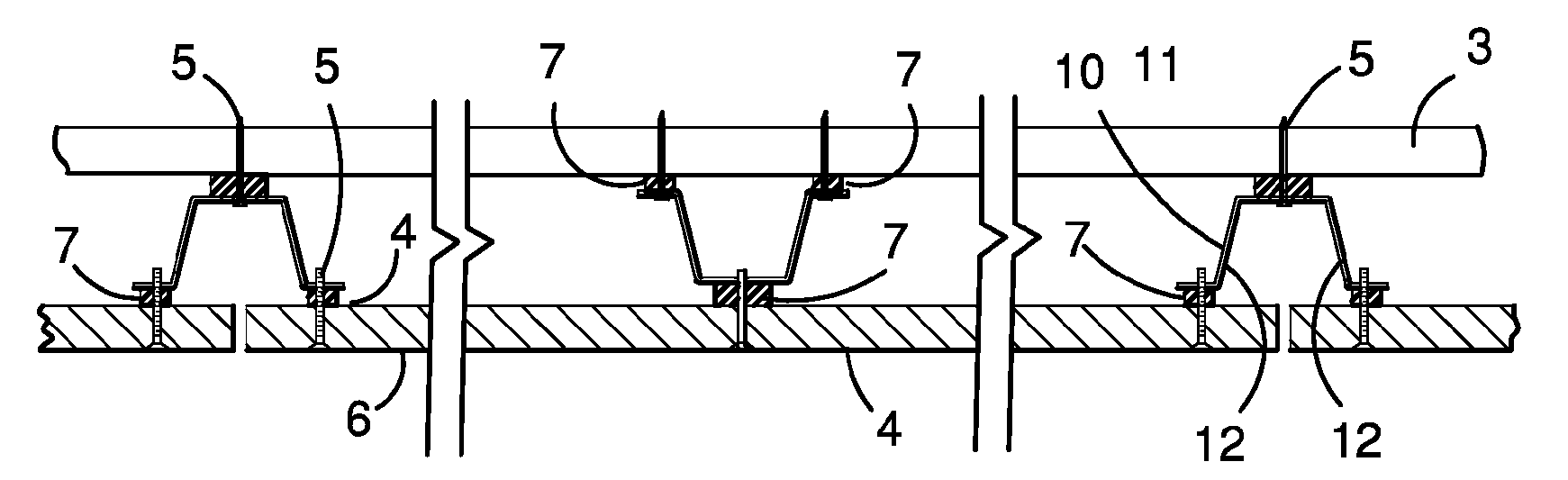
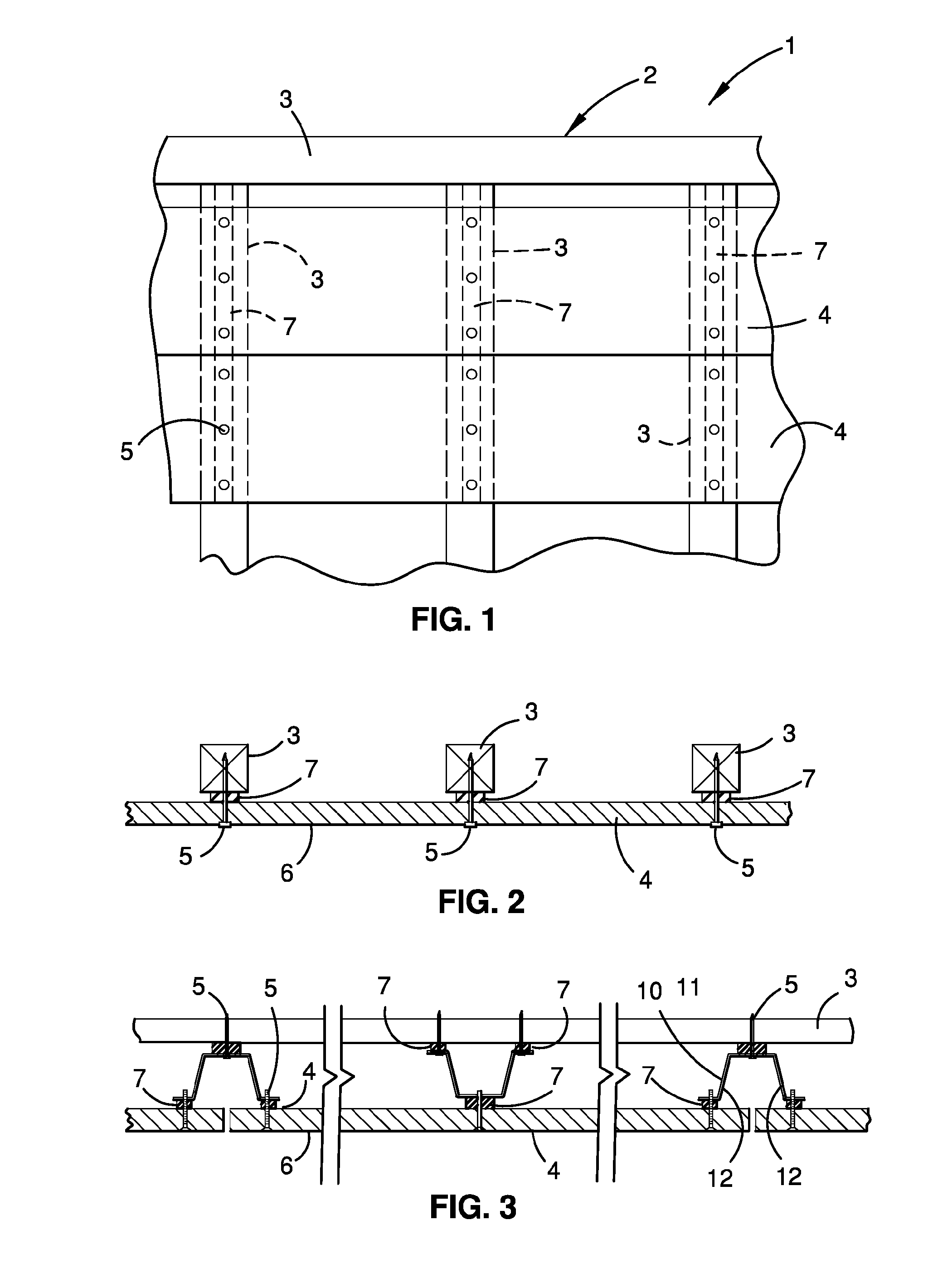
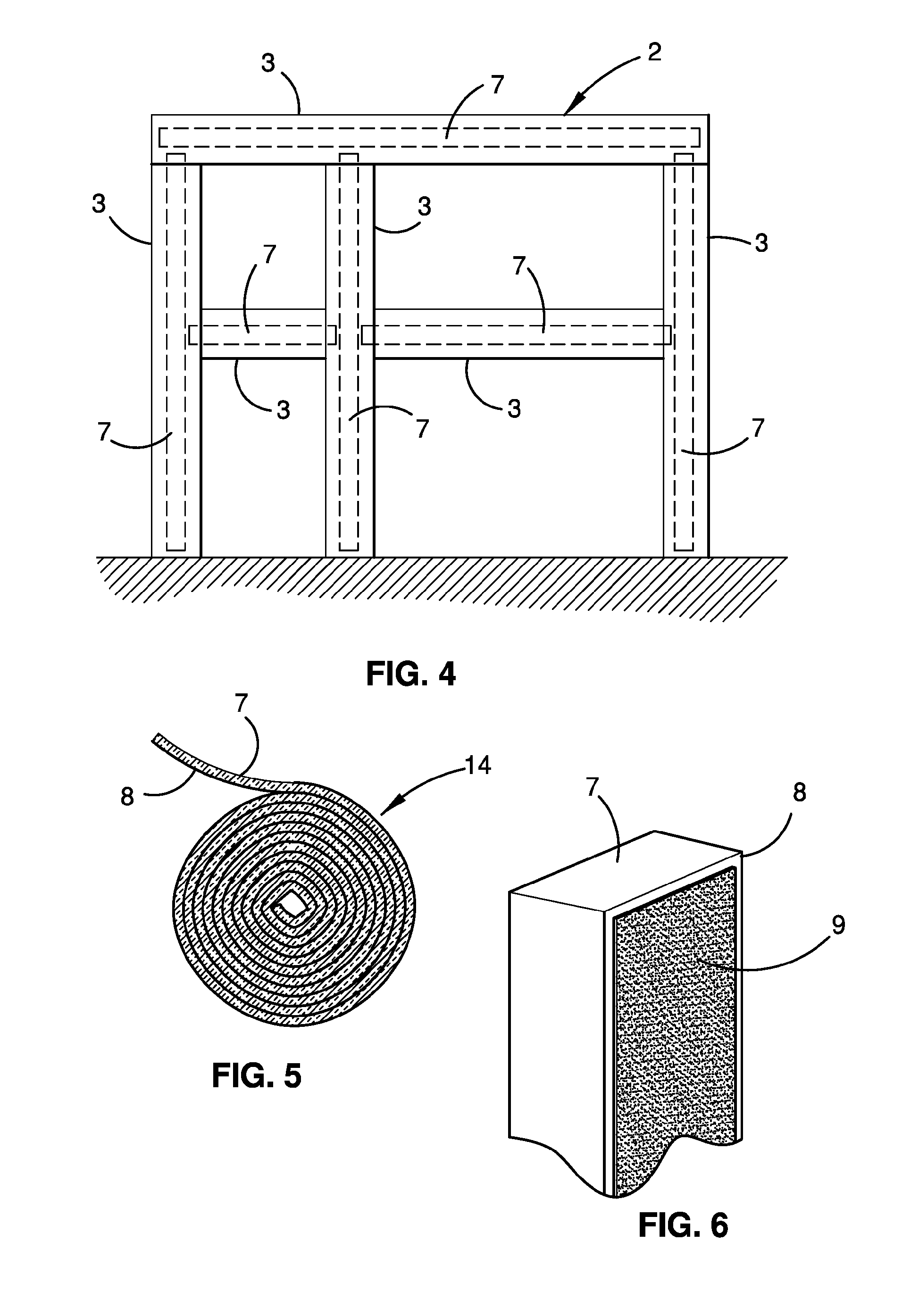
[0064]Referring to the drawings, the building section 1 includes a sub-structure in the form of a frame 2. The frame 2 is formed from a series of interconnected frame members 3 including a plurality of substantially vertical frame members and a plurality of substantially horizontal frame members. As will be described in greater detail below, the frame members 3 may be made from timber or metal such as steel.

[0065]For the sake of clarity, the following description will be made with reference to a wall frame. However, those skilled in the art will appreciate that the frame 2 may be a section of any suitable building frame including a wall frame, a sub-floor frame, a ceiling frame and a roof frame. It will be further appreciated by those skilled in the art that the present invention is not limited to the sub-structures listed here. In addition, it is to be understood that certain frames may be inclined, rather than being arranged to lie in a substantially vertical or horizontal plane.

[...


PUM

PropertyMeasurementUnit
densityaaaaaaaaaa
compressive strengthaaaaaaaaaa
thermal conductivityaaaaaaaaaa

Abstract

The invention relates to a building section including a sub-structure and a cladding member connected in fixed relation relative to the sub-structure. A multi-function elongate, flexible insulating element is disposed between the sub-structure and the cladding member for damping energy transfer between the cladding member and the sub-structure, facilitating alignment of the cladding, and creating a rainscreen configured to drive out moisture from the wall cavities. In some implementations, the insulating element has at least one insulating layer which is substantially incompressible and which has a substantially constant density in the range of 200 kg/m3 to 300 kg/m3. In certain preferred implementations, the insulating element can be formed of a foam material such as foam tape or thermal break tape.

Description

REFERENCE TO RELATED APPLICATIONS[0001]This application is a continuation-in-part of PCT Application Number PCT / AU2010 / 001065 filed Aug. 20, 2010 which claims priority to Australian Patent No. 2009903931 filed Aug. 20, 2009 which are hereby incorporated by reference in their entirety herein.FIELD OF THE INVENTION[0002]The present invention relates generally to the field of building systems and, in particular, to systems incorporating the use of improved materials and construction techniques for insulating, facilitating alignment, and / or providing a rainscreen for a section of a building.[0003]The invention has been developed specifically for use in connection with internal and external cladding systems and will be described primarily with reference to this application.BACKGROUND OF THE INVENTION[0004]The following discussion of the prior art is intended to enable the invention to be placed in an appropriate technical context and to allow the advantages of it to be fully appreciated....

Claims


Application Information

Patent Timeline
Patent Type & Authority Applications(United States)
IPC IPC(8): E04B2/44E04B1/62E04B1/66E04C2/20
CPCE04B2/7409E04B9/245E04B2/7457
Inventor MILOSTIC, ANTHONY
Owner JAMES HARDIE TECH LTD
Why Eureka
Try Eureka