Split-Ring Gland Pipe Coupling with Corrugated Armor

Active Publication Date: 2012-08-16
SENSUS SPECTRUM LLC
View PDF11 Cites 31 Cited by
  • Summary
  • Abstract
  • Description
  • Claims
  • Application Information

AI Technical Summary

Benefits of technology

[0005]The present invention in one aspect provides an improved armor for the split-ring gland type of pipe couplings. The conventional armor is cold formed of stainless steel and presents a generally flat, smooth surface to the outer periphery of the gasket. In accordance with the principles of the present invention, at least a portion of the gasket confronting surface is corrugated, i.e., it

Problems solved by technology

Also, during installation with conventional armors, the gasket would tend to “bunch up” at the ends of the armor, making it difficult to properly install the pipe coupling.
But the lubrication further hampers installation as the components are more difficult to handle and can hold dirt and ot

Method used


Image

  • Split-Ring Gland Pipe Coupling with Corrugated Armor
  • Split-Ring Gland Pipe Coupling with Corrugated Armor
  • Split-Ring Gland Pipe Coupling with Corrugated Armor

Examples


Example

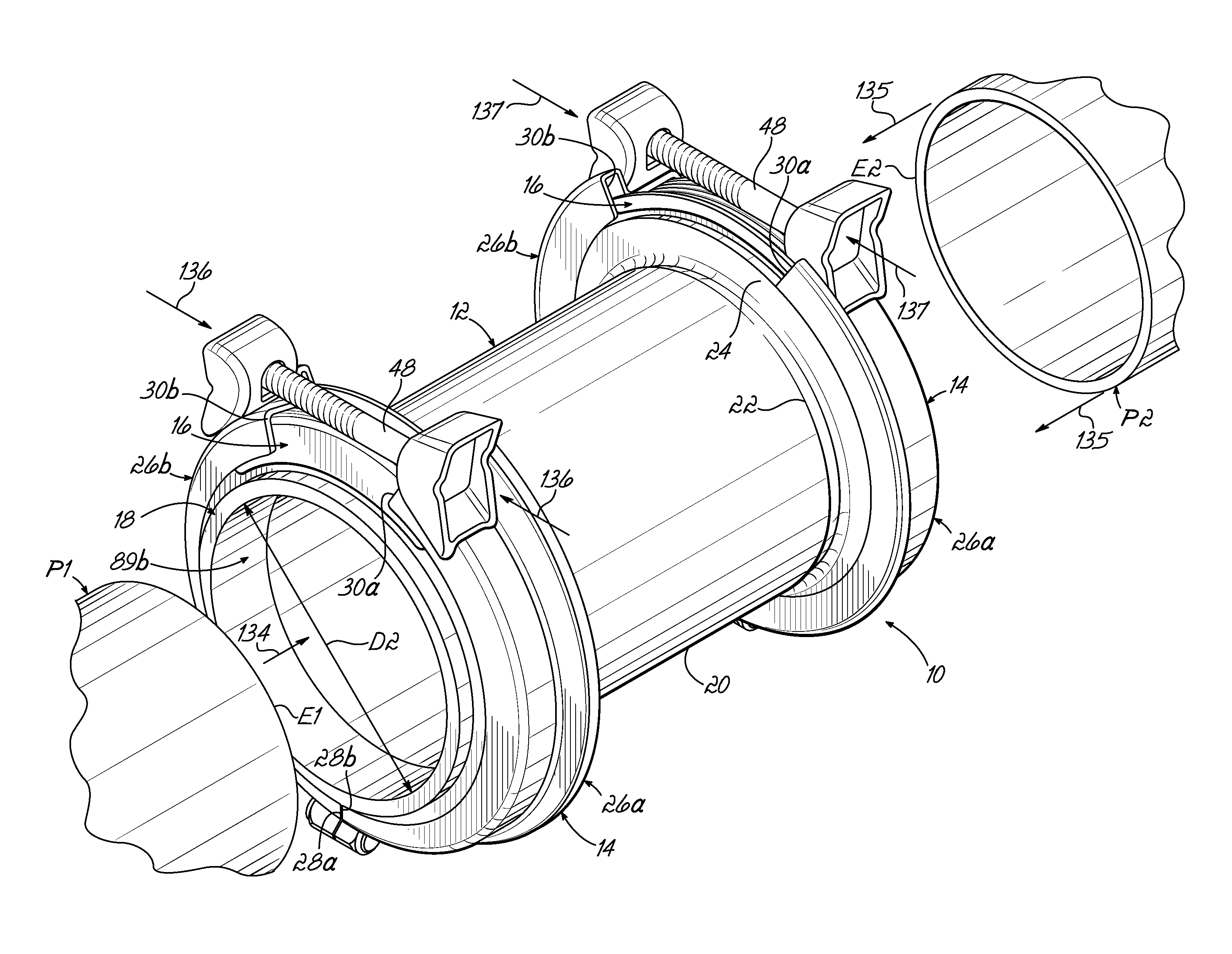
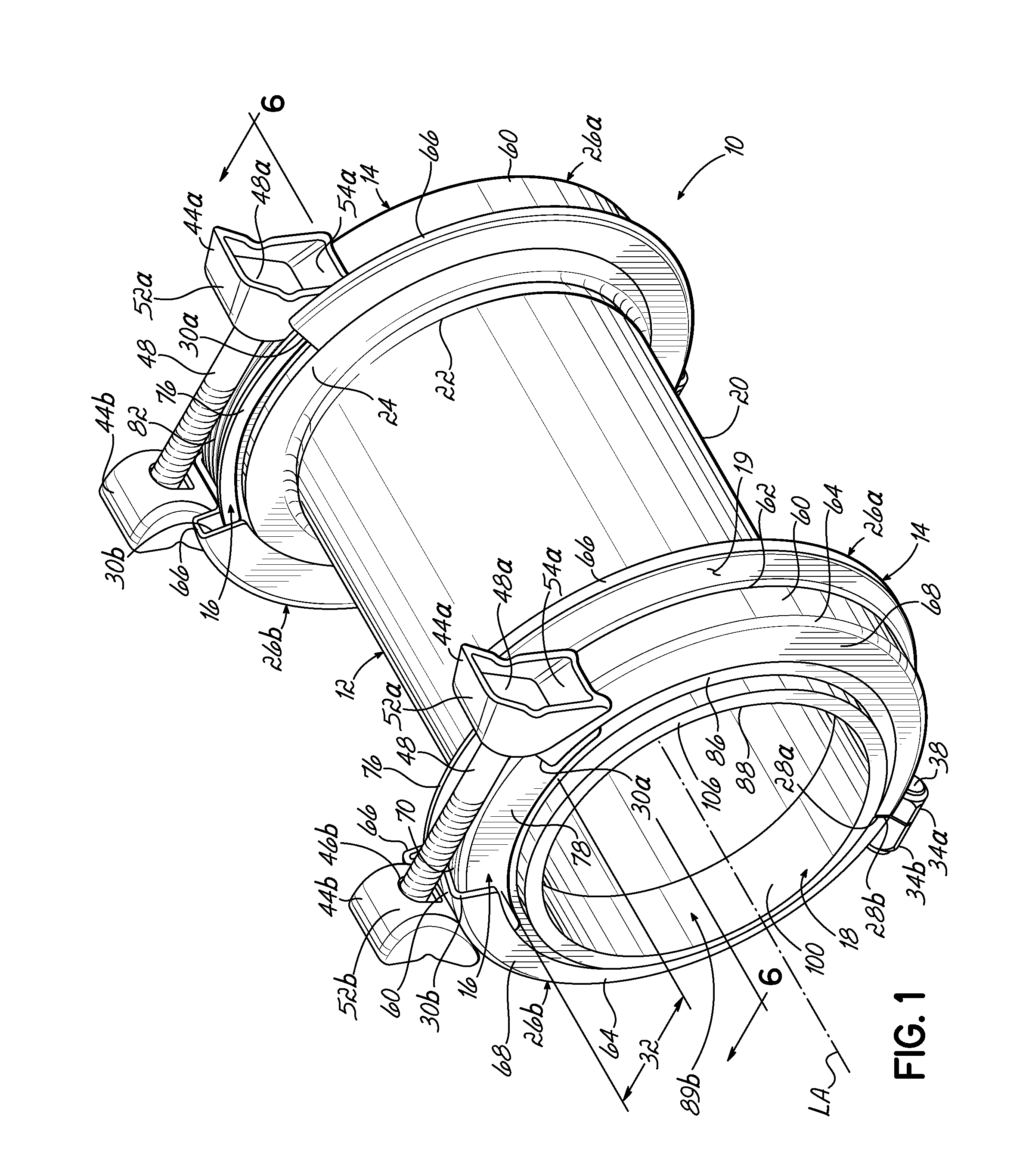
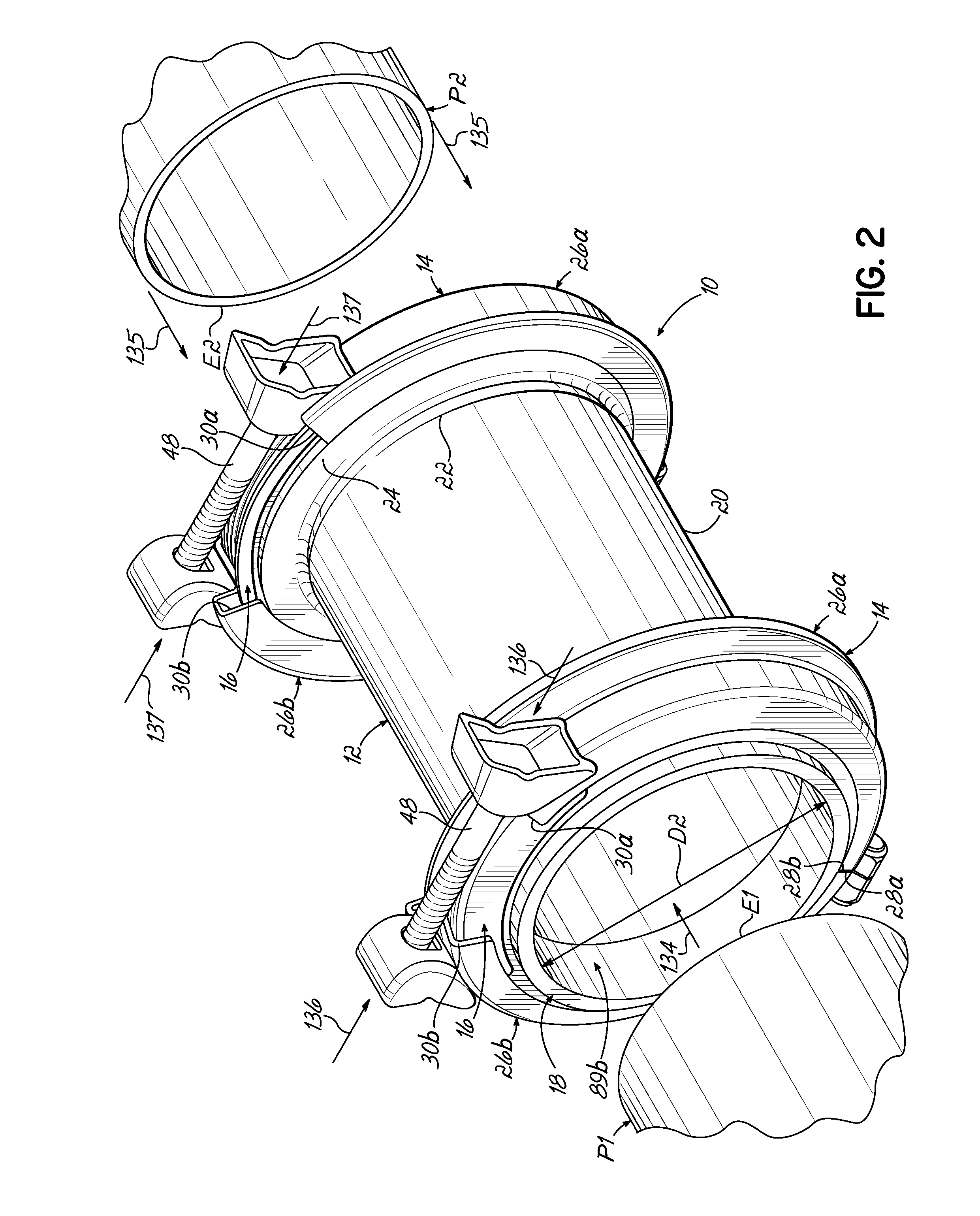
[0020]With reference to FIGS. 1 and 2, a split-ring gland type of pipe coupling 10 according to one embodiment of the present invention is shown. The pipe coupling 10 includes a sleeve 12, a pair of split-ring glands 14, a bridge plate or armor 16 associated with each split-ring gland 14, and an annular gasket 18 associated with each split-ring gland 14. In the fully assembled state of the pipe coupling 10, an end E1 of a first pipe P1 is inserted into the sleeve 12 through one of the split-ring glands 14 and the corresponding gasket 18, and an end E2 of a second pipe P2 is inserted into the other split-ring gland 14 and associated gasket 18. The split-ring glands 14 are configured to be tightened onto the corresponding gaskets 18 to compress the gaskets 18 into sealing connection with the respective pipe ends E1, E2. The split-ring gland 14 and the armor 16 collectively define a generally closed annular periphery 19 around the gasket 18, which further ensures that fluid passing thr...


PUM

PropertyMeasurementUnit
Lengthaaaaaaaaaa
Diameteraaaaaaaaaa
Sizeaaaaaaaaaa

Abstract

A pipe coupling for coupling adjacent ends of a pair of pipes includes a sleeve, a split-ring gland positioned around one of the ends of the sleeve, and at least one annular gasket positioned within the split-ring gland and configured to be compressed by the split-ring gland for sealing one pipe end to the sleeve. The split-ring gland includes two partially circular gland members with spaced ends defining a gap. The pipe coupling includes an armor positioned to span the gap between the spaced ends to provide a generally closed annular periphery about the gasket. The armor includes a corrugated portion having a plurality of corrugations engaging the split-ring gland and the gasket during compression of the gasket. The armor is cold formed to improve structural strength and durability.

Description

FIELD OF THE INVENTION[0001]The present invention relates generally to pipe couplings and joints and, more particularly, to pipe couplings adapted to couple and seal adjacent ends of two pipe sections of the same or different diameters.BACKGROUND OF THE INVENTION[0002]Conventional pipe couplings for coupling and sealing adjacent ends of two pipe sections include a coupling sleeve or collar with each pipe end extending into a respective end of the coupling sleeve. A gasket is held adjacent each end of the sleeve overlying the pipe section. An annular flange or gland is associated with each gasket and end of the sleeve, and is tightened to draw down the gasket against the pipe end thus sealing the pipe coupling thereto. One pipe coupling is shown in my prior U.S. Pat. No. 6,168,210 and utilizes continuous flanges that are coupled together via bolts spanning the sleeve. The flanges, sleeve ends, and gaskets have particular relationships that affect the seal and allow the coupling to wo...

Claims


Application Information

Patent Timeline
IPC IPC(8): F16L21/02B23P11/00F16J15/06
CPCF16L21/022F16L21/08F16L19/00F16L21/065Y10T29/49908F16L19/0206Y10T29/49947Y10T29/49826Y10T29/49948B23P11/00
Inventor BIRD, EDWIN A.
Owner SENSUS SPECTRUM LLC
Why Eureka
Try Eureka