

Non-360 Degree Driving Brushless DC Motor
a dc motor and 360-degree driving technology, applied in the field of motors, can solve the problems of inconvenient assembly and inevitable increase in production costs, and achieve the effect of accurate load matching and easy adjustmen
- Summary
- Abstract
- Description
- Claims
- Application Information
AI Technical Summary
Benefits of technology
Problems solved by technology
Method used
Image

Examples
first embodiment
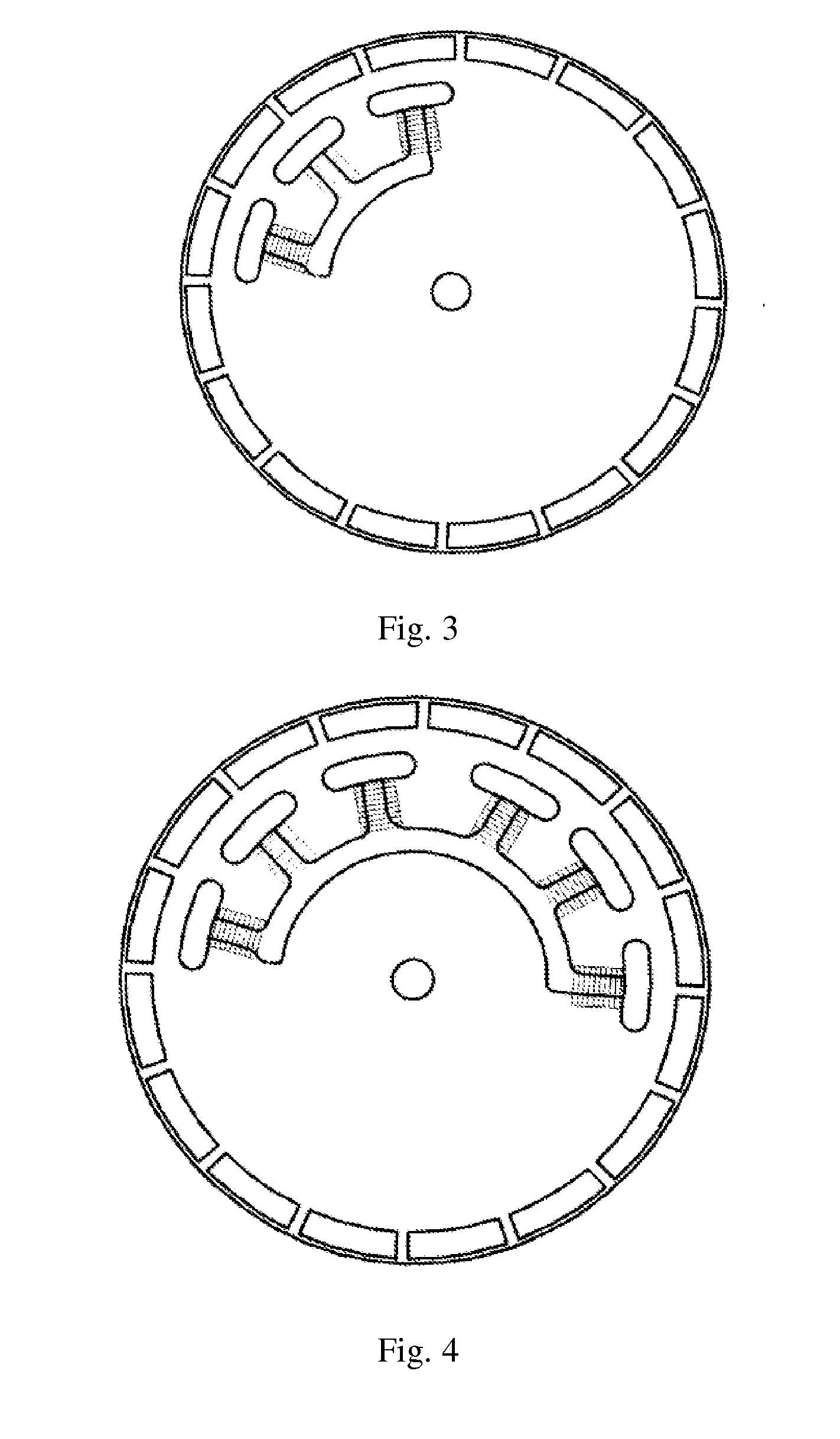
[0039]FIG. 3 illustrates the invention. In the embodiment, the number of the stator coils is unchanged, the number of the magnetic poles of the rotor is changed from 4 to 16, the radius of the rotor is changed from 7 mm to 28 mm, and other parameters are the same as those of the motor shown in FIG. 1.
[0040]As shown in FIG. 3, when the positions of the stator coils of the motor are set, 3 coils are not evenly arranged along the circumference of the stator, but the positions of the 3 coils on the circumference of the stator are set as the circumferential angle occupied by the 3 coils together corresponds to the circumferential angle occupied by 4 continuous magnetic poles on the rotor.
[0041]According to the revolving speed formula of the brushless DC motor:
r=120f / p,
wherein, f represents the frequency of the stator current, p represents the number of the magnetic poles of the rotor, and r represents the revolving speed. When other parameters are unchanged and only the number of the ma...
second embodiment
[0042]FIG. 4 illustrates the invention. In the embodiment, the number of the stator coils is 6, the number of the magnetic poles of the rotor is 16, the radius of the rotor is 28 mm, and other parameters are the same as those of the motor shown in FIG. 1. According to the revolving speed formula of the brushless DC motor:
r=120f / p,
the revolving speed of the motor in the embodiment is 5,000*4 / 16=1,250 rpm. Meanwhile, according to the torque formula, the output torque is 0.05*(28 / 7)*(6 / 3)=0.4 N·m.
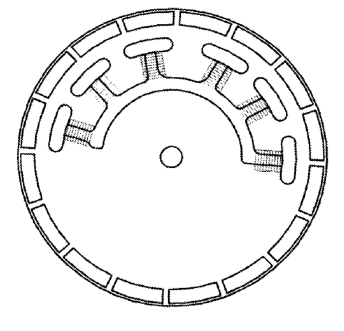
[0043]As shown in FIG. 4, 6 coils are not evenly arranged along the circumference of the stator, but the positions of the 6 coils on the circumference of the stator are set as the circumferential angle occupied by the 6 coils together corresponds to the circumferential angle occupied by 8 continuous magnetic poles on the rotor.
third embodiment
[0044]FIG. 5 illustrates the invention. In the embodiment, the number of the stator coils is 3, the number of the magnetic poles of the rotor is 18, the radius of the rotor is 32 mm, and other parameters are the same as those of the motor shown in FIG. 1. According to the revolving speed formula of the brushless DC motor:
r=120f / p,
the revolving speed of the motor in the embodiment is 5,000*4 / 18=1,111 rpm. Meanwhile, according to the torque formula, the output torque is 0.05*(32 / 7)=0.23 N·m.
PUM
| Property | Measurement | Unit |
|---|---|---|
| Length | aaaaa | aaaaa |
| Angle | aaaaa | aaaaa |
| Diameter | aaaaa | aaaaa |
Abstract
Description
Claims
Application Information