Heart Valve Stent

Inactive Publication Date: 2012-11-08
LUTTER GEORG +1
View PDF2 Cites 211 Cited by
  • Summary
  • Abstract
  • Description
  • Claims
  • Application Information

AI Technical Summary

Benefits of technology

[0016]The basic idea of the invention is to produce a heart valve stent which establishes the anatomic requirements for the natural exertion of the function—like a healthy heart. In the process, the invention-related heart valve stent with its self-expanding, foldable embodiment establishes a minimally-invasive operation which assures an exact posit

Problems solved by technology

Even with the known solutions there is still the danger that a heart valve is mal-implanted due to wrong positioning and deficient angular adjustment of the heart valve prostheses.
A much larger problem for the optimal positioning of the new heart valve in the stent (alternatively valved stent) still exists in the following: in most cases the old, native v

Method used


Image

  • Heart Valve Stent
  • Heart Valve Stent
  • Heart Valve Stent

Examples


Embodiment Construction

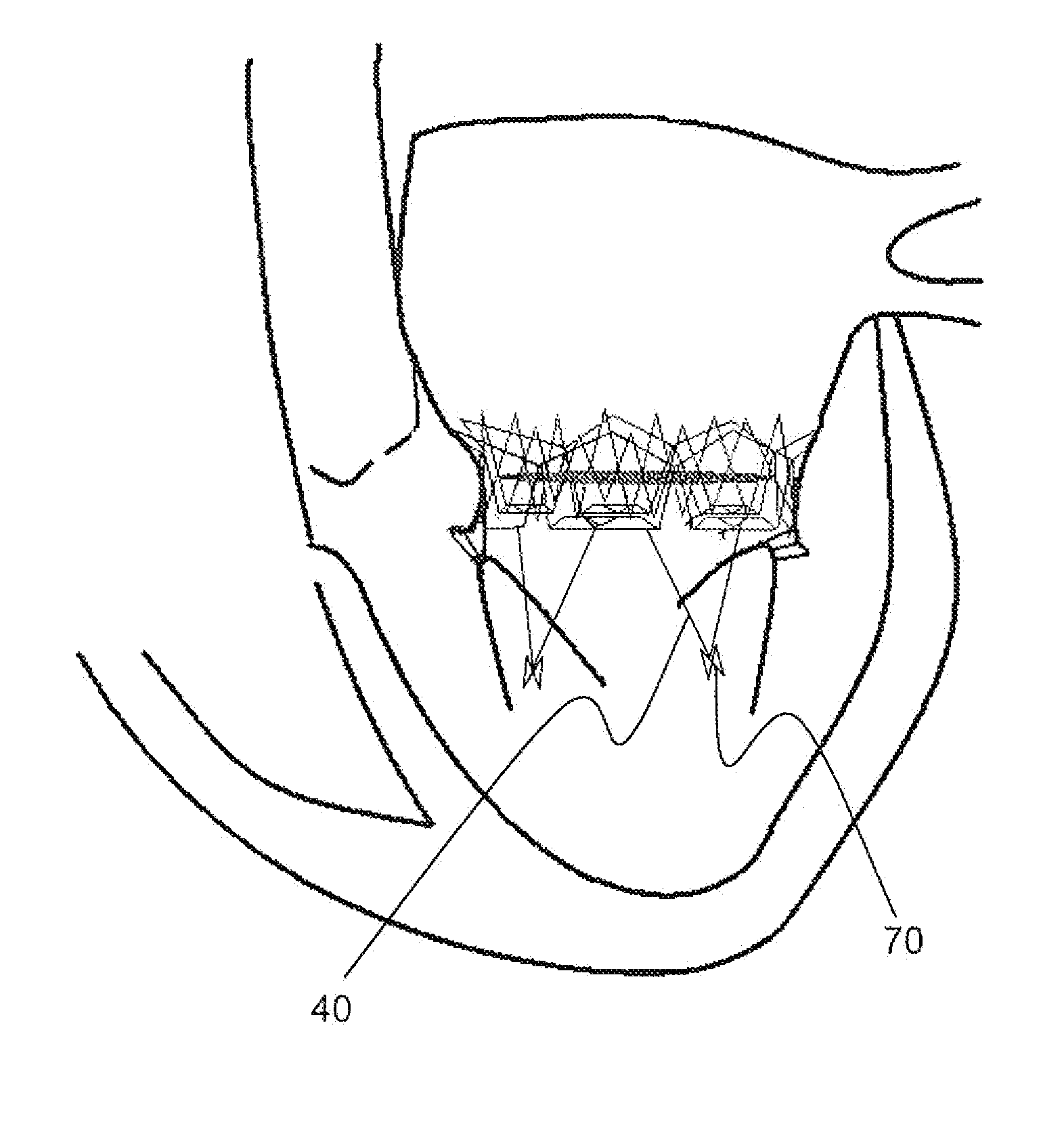
[0041]FIGS. 1 to 11 indicate the stent according to the invention for the implantation and fixation of heart valve prostheses in different views to show the configuration of the stents and the spatial relations of individual parts of the stent to each other in an unfolded (FIGS. 1-4 and 6-11) and in a folded condition (FIG. 5).

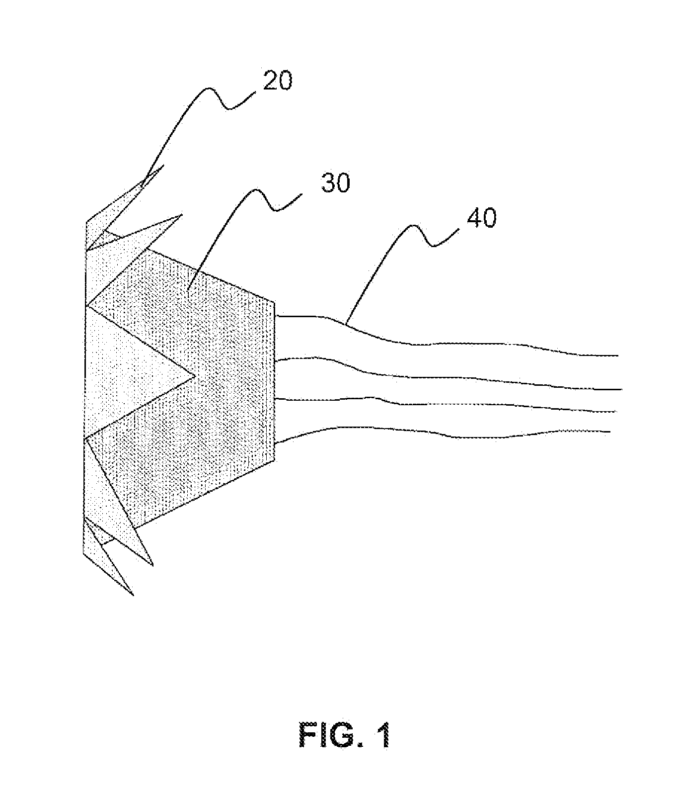
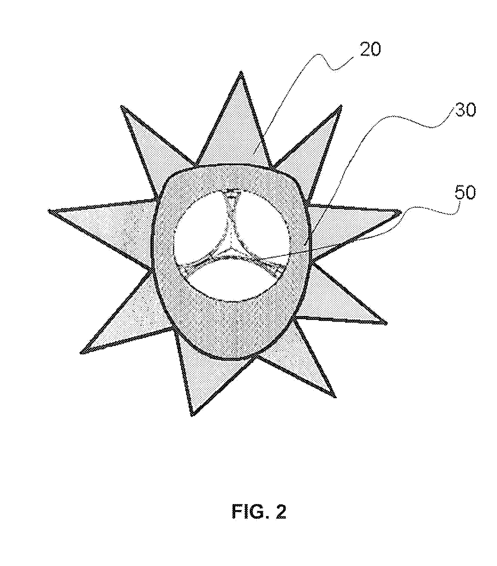
[0042]FIG. 1 shows a foldable mitral valve stent 10 according to the invention in a perspective lateral view. The stent 10 exhibits mainly three parts: proximally (supravalvularly) on stent 10 there are several serrated, arched anchoring (FIG. 3) elements 20 circularly arranged which are able to anchor supravalvularly (respectively atrially) the valve stent 10 in an implanted condition. The preferable stent body 30 flattened to the LVOT is distally adjoined and is conical and in cross section ovally shaped (compare FIG. 2).

[0043]The stent body 30 forms a basket- or trapezoid-like figure which nestles to the mitral valve annulus and extends in the direction of ...


PUM


Abstract

A heart valve stent having a section equipped to receive a heart valve implant and several proximally disposed anchoring elements, characterized by several anchoring threads, which with the one end thereof are fastened to the stent, and also with a brace fastening the anchoring threads with the other end thereof to the distal chamber wall to provide tension between the heart chamber wall and the proximally anchored anchoring elements.

Description

CROSS-REFERENCE TO RELATED APPLICATIONS[0001]This application represents a continuation of U.S. application Ser. No. 12 / 677,958, filed Sep. 9, 2010, pending, a National Stage application of PCT / DE2008 / 001515 entitled “Heart Valve Stent”, filed Sep. 10, 2008.BACKGROUND OF THE INVENTION[0002]The invention refers to a valve stent with a section equipped to receive a heart valve implant and several of proximally disposed anchoring elements.[0003]Such heart valve stents are known in various forms for the replacement dysplastic and degenerated heart valves. Thereby, the surgical implantation of heart valve prostheses is regularly accomplished in the cardioplegic heart. The old, functionally degenerated heart valve is resected and the new, implantable heart valve is sewed in.[0004]However, when the mitral valve is affected, one tries, as far as possible, to maintain the old valve in spite of its malfunctioning so that the entire dynamic mital valve apparatus is not disturbed. The reason fo...

Claims


Application Information

Patent Timeline
IPC IPC(8): A61F2/82
CPCA61F2/2457A61F2/2487A61B17/0401A61B2017/00243A61B2017/0496A61F2230/0078A61F2/2436A61F2250/001A61F2220/0008A61F2230/005A61F2230/0054A61F2/2418A61F2230/0067A61F2230/0069A61F2230/0008A61F2230/0013A61F2/2445
Inventor LUTTER, GEORGLOZONSCHI, LUCIAN
Owner LUTTER GEORG
Why Eureka
Try Eureka