

Antiseptic Cap Equipped Syringe
a technology of anti-thrombosis cap and syringe, which is applied in the direction of catheters, intravenous devices, other medical devices, etc., can solve the problems of catheter thrombosis, catheter occludement, and catheter occludement, so as to prevent relative rotational movement
- Summary
- Abstract
- Description
- Claims
- Application Information
AI Technical Summary
Benefits of technology
Problems solved by technology
Method used
Image

Examples
Embodiment Construction
[0133]While this invention is susceptible of embodiment In many different forms, there is shown in the drawings, and will be described herein in detail, specific embodiments thereof with the understanding that the present disclosure is to be considered as an exemplification of the principles of the invention and is not intended to limit the invention to the specific embodiments illustrated.
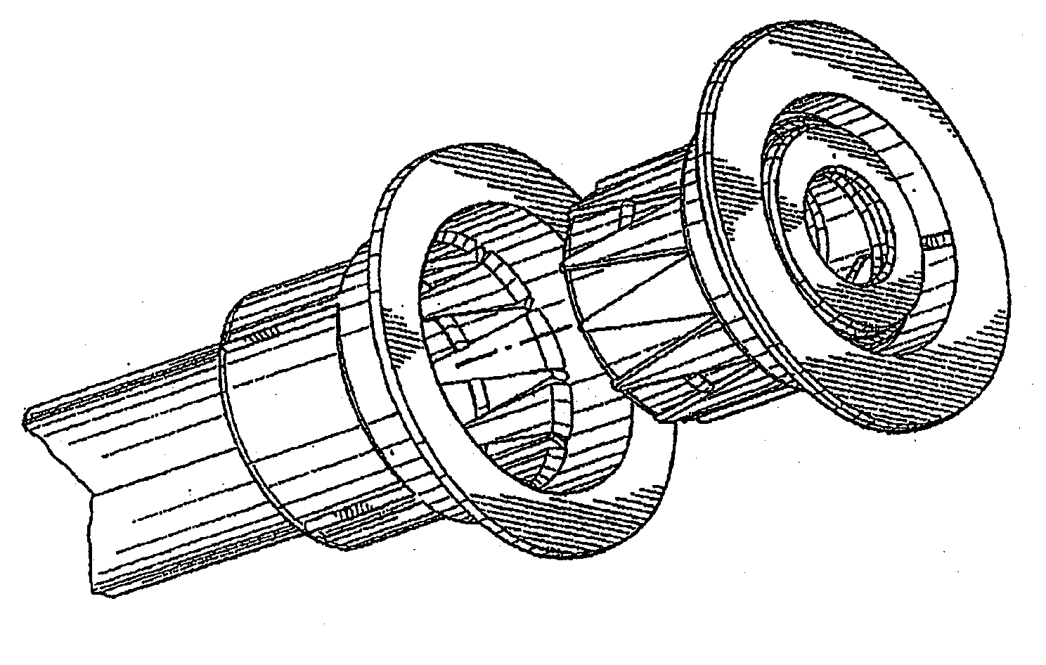
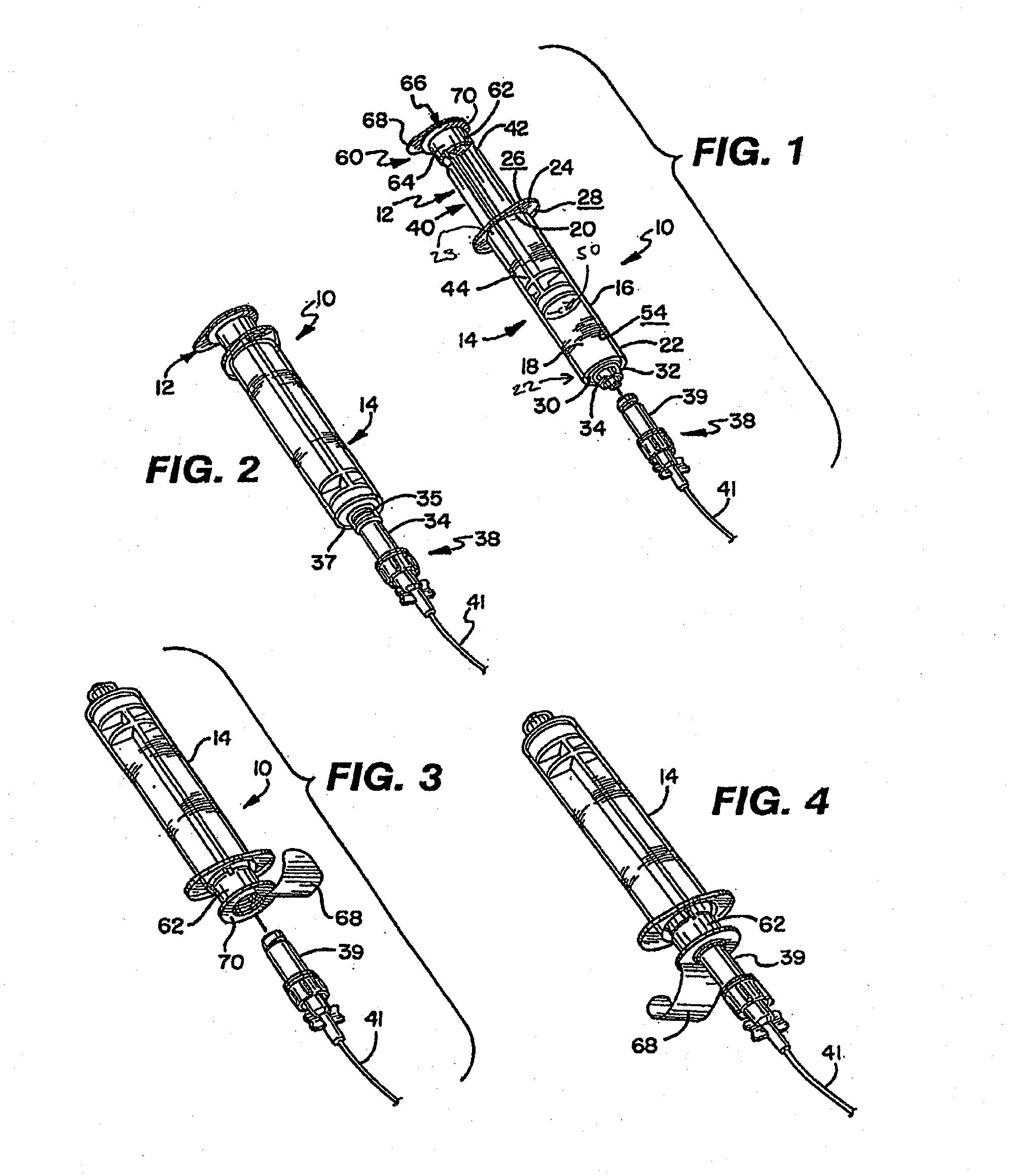
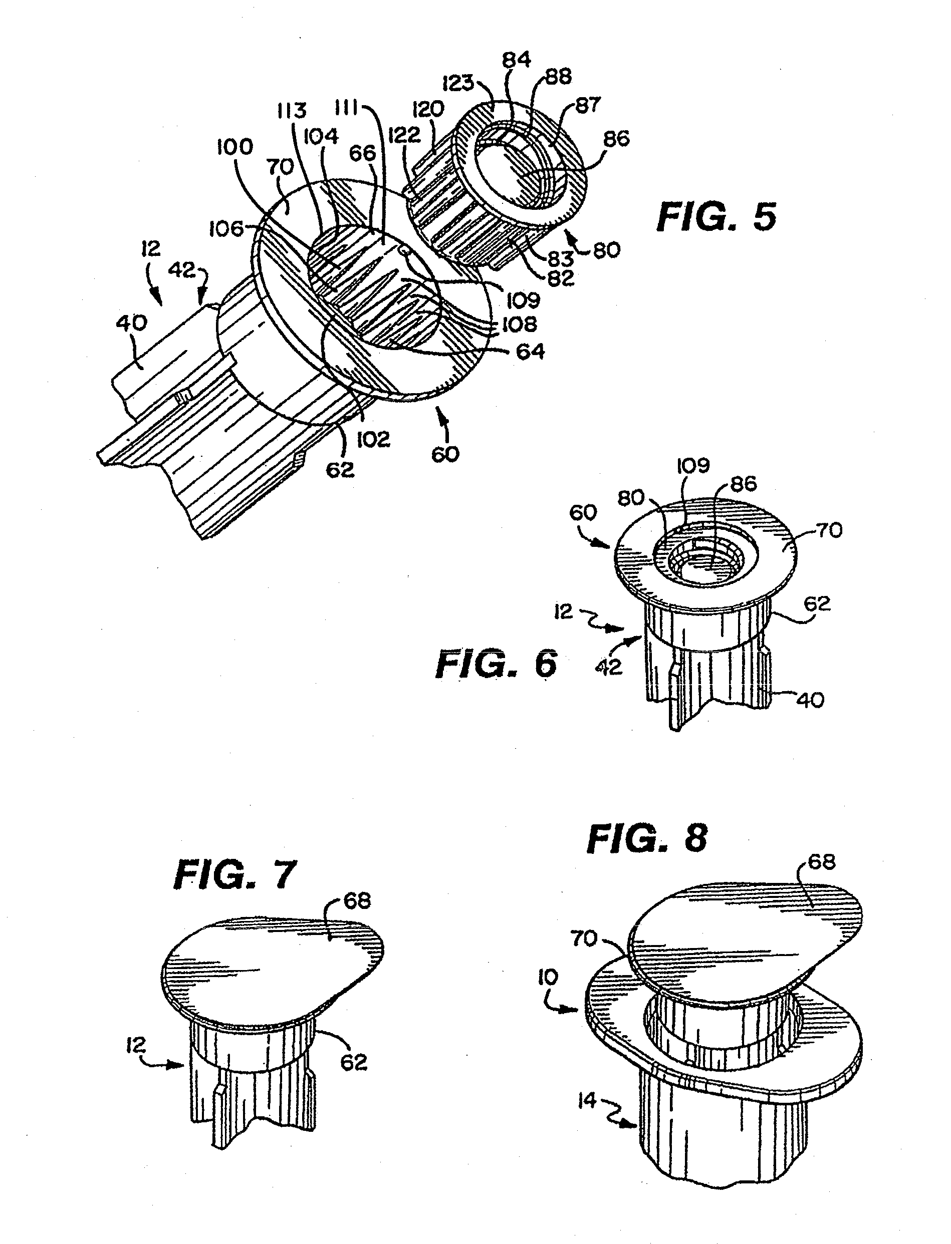
[0134]FIGS. 1 and 2 show an antiseptic cap equipped plunger and syringe barrel assembly 10 having an antiseptic cap equipped plunger (or piston) assembly 12 and a syringe barrel 14. The barrel 14 has a side wall 16 defining a chamber 18 and the barrel has a proximal end 20 and a distal end 22. The proximal end 20 has an opening 22 to the chamber 18 and a flange 24 extending radially outwardly from the wall 16. The flange 24 has upper and lower surfaces 26, 28 and provides gripping surfaces for a user of the assembly 10. The distal end 22 of the barrel 14 has an end wall 30 and an elongate tip 32 e...
PUM
 Abstract
Description
Claims
Application Information