Finger guard for an injection device

a technology of injection device and finger guard, which is applied in the direction of injection needles, intravenous devices, automatic syringes, etc., can solve the problems of user delivery of an underdose, user's injection force may be too high, and the user's mental and physical risks,

Active Publication Date: 2013-07-25
SANOFI AVENTIS DEUT GMBH
View PDF6 Cites 44 Cited by
  • Summary
  • Abstract
  • Description
  • Claims
  • Application Information

AI Technical Summary

Benefits of technology

[0010]It is an object of the present invention to provide a finger guard for protecting a user's fingers from needle-stick injuries when a protective needle shield is removed from a needle.

Problems solved by technology

Administering an injection is a process which presents a number of both mental and physical risks and challenges for users and healthcare professionals.
There are numerous disadvantages to the user from this approach.
This means that the user can deliver an under dose if the device is not used properly (i.e. the plunger is not fully pressed to its end position).
Injection forces may be too high for the user, in particular if the patient is elderly or has dexterity problems.
The extension of the button / plunger may be too great.
Thus it can be inconvenient for the user to reach a fully extended button.
The combination of injection force and button extension can cause trembling / shaking of the hand which in turn increases discomfort as the inserted needle moves.
In this situation the risk for needle stick injuries is more or less increased depending on the design of the syringe or the injection device.

Method used


Image

  • Finger guard for an injection device
  • Finger guard for an injection device
  • Finger guard for an injection device

Examples


Embodiment Construction

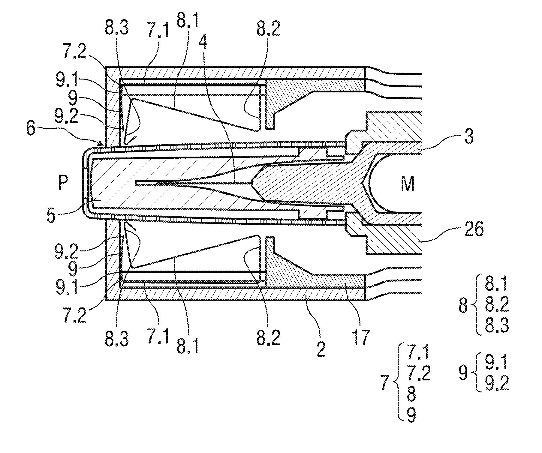
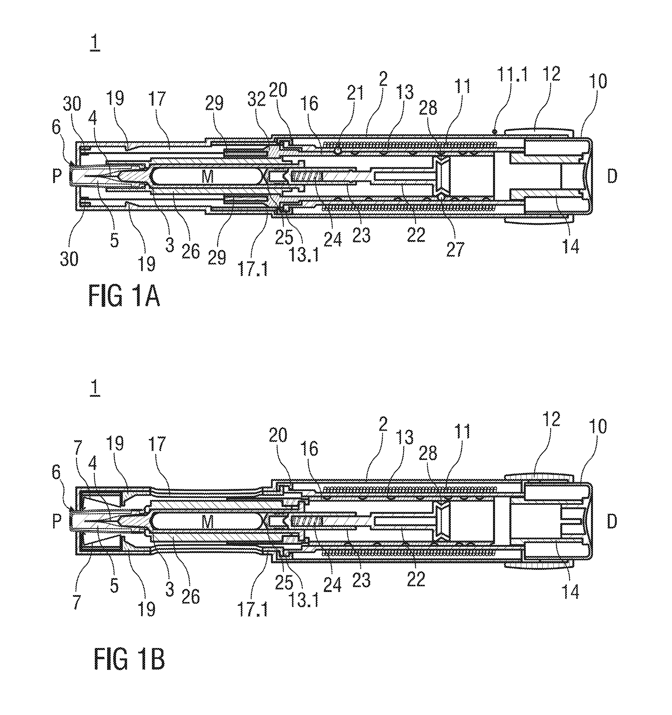
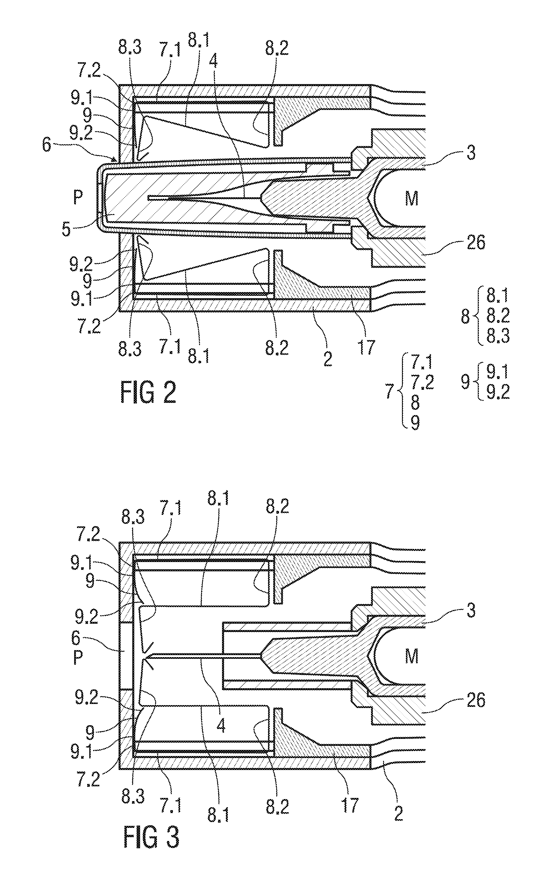
[0115]FIG. 1 shows two longitudinal sections in different section planes of an auto-injector 1, the different section planes approximately 90° rotated to each other. The auto-injector comprises an elongate outer casing 2. A syringe 3 with a hollow needle 4 is arranged in a proximal part of the auto-injector 1. When the auto-injector 1 is assembled a protective needle shield 5 is attached to the needle 4 and protruding through an orifice 6 at the proximal end P. A finger guard 7 in the shape of a sheet metal spring is arranged near the protective needle shield 5. The finger guard 7 comprises two spring arms 8 which are inwardly biased so they bear against the protective needle shield 5 as long as it is still in place. A respective locking arm 9 is assigned to each spring arm 8. The locking arms 9 are biased in distal direction D so they bear against a part of the spring arms 8 when the protective needle shield 5 is in place. As the protective needle shield 5 is pulled away from the n...


PUM


Abstract

The invention relates to a finger guard (7) for an injection device for administering a dose of a liquid medicament (M), the finger guard (7) comprising two inwardly biased spring arms (8) arranged for bearing against a protective needle shield (5) arrangeable at a hollow needle (4), the finger guard (7) further having a respective locking arm (9) assigned to each spring arm (8) biased in a distal direction (D) thus bearing against the respective spring arm (8) when the protective needle shield (5) is in place, wherein the spring arms (8) are arranged to move inwards when the protective needle shield (5) is removed thus allowing the locking arms (9) to move distally into a position where they prevent the spring arms (8) from being pushed outward again.

Description

TECHNICAL FIELD[0001]The invention relates to a finger guard for an injection device.BACKGROUND OF THE INVENTION[0002]Administering an injection is a process which presents a number of both mental and physical risks and challenges for users and healthcare professionals.[0003]Injection devices (i.e. devices capable of delivering medicaments from a medication container) typically fall into two categories—manual devices and auto-injectors.[0004]In a manual device—the user must provide the mechanical energy to drive the fluid through the needle. This is typically done by some form of button / plunger that has to be continuously pressed by the user during the injection. There are numerous disadvantages to the user from this approach. If the user stops pressing the button / plunger then the injection will also stop. This means that the user can deliver an under dose if the device is not used properly (i.e. the plunger is not fully pressed to its end position). Injection forces may be too high...

Claims


Application Information

Patent Timeline
Patent Type & Authority Applications(United States)
IPC IPC(8): A61M5/32
CPCA61M5/2033A61M5/3146A61M5/31575A61M5/3202A61M5/3204A61M5/321A61M5/3245A61M5/422A61M5/46A61M2005/206A61M2005/2073A61M2005/31516A61M2005/325A61M5/326
Inventor EKMAN, MATTHEWBARROW-WILLIAMS, TIMOTHY DONALDHOURMAND, YANNICK
Owner SANOFI AVENTIS DEUT GMBH
Why Eureka
Try Eureka