Transillumination of body members for protection during body invasive procedures

a technology of body parts and transilluminated ureters, applied in medical science, surgery, diagnostics, etc., can solve the problem that the camera cannot detect light emanating from the transilluminated ureter, and achieve the effect of reducing glar

Inactive Publication Date: 2003-07-22
STRYKER CORP
View PDF2 Cites 41 Cited by
  • Summary
  • Abstract
  • Description
  • Claims
  • Application Information

AI Technical Summary

Benefits of technology

It is another object of the present invention to provide a system and method permitting ease of discrimination of light energy emanating from a body member to be protected during an invasive procedure adjacent said body member from light introduced to illuminate the region of the procedure adjacent such body member.
Still another object of the present invention is to transmit infrared light through a body part to be protected during a surgical procedure and to maintain the surgical site otherwise free of infrared energy by filtering out infrared energy from an endoscopic or other light source if such is employed.
Still another object of the present invention is to synchronize a camera shutter with periodic emission of light into a region being subjected to an invasive procedure with periodic emission of detectable energy from a body member to be protected from injury during such invasive procedure.
Yet another object of the present invention is to transilluminate a body member or region with infrared energy to enhance the view of the region whereby to facilitate a surgical procedure.

Problems solved by technology

In the presence of the normally illuminated operative field from the endoscopic light, the camera frequently cannot detect light emanating from the transilluminated ureter.
The same problems are encountered in open field surgery where the overhead lights in the operating room may have as great an effect as the endoscopic light source.

Method used


Image

  • Transillumination of body members for protection during body invasive procedures
  • Transillumination of body members for protection during body invasive procedures
  • Transillumination of body members for protection during body invasive procedures

Examples


Embodiment Construction

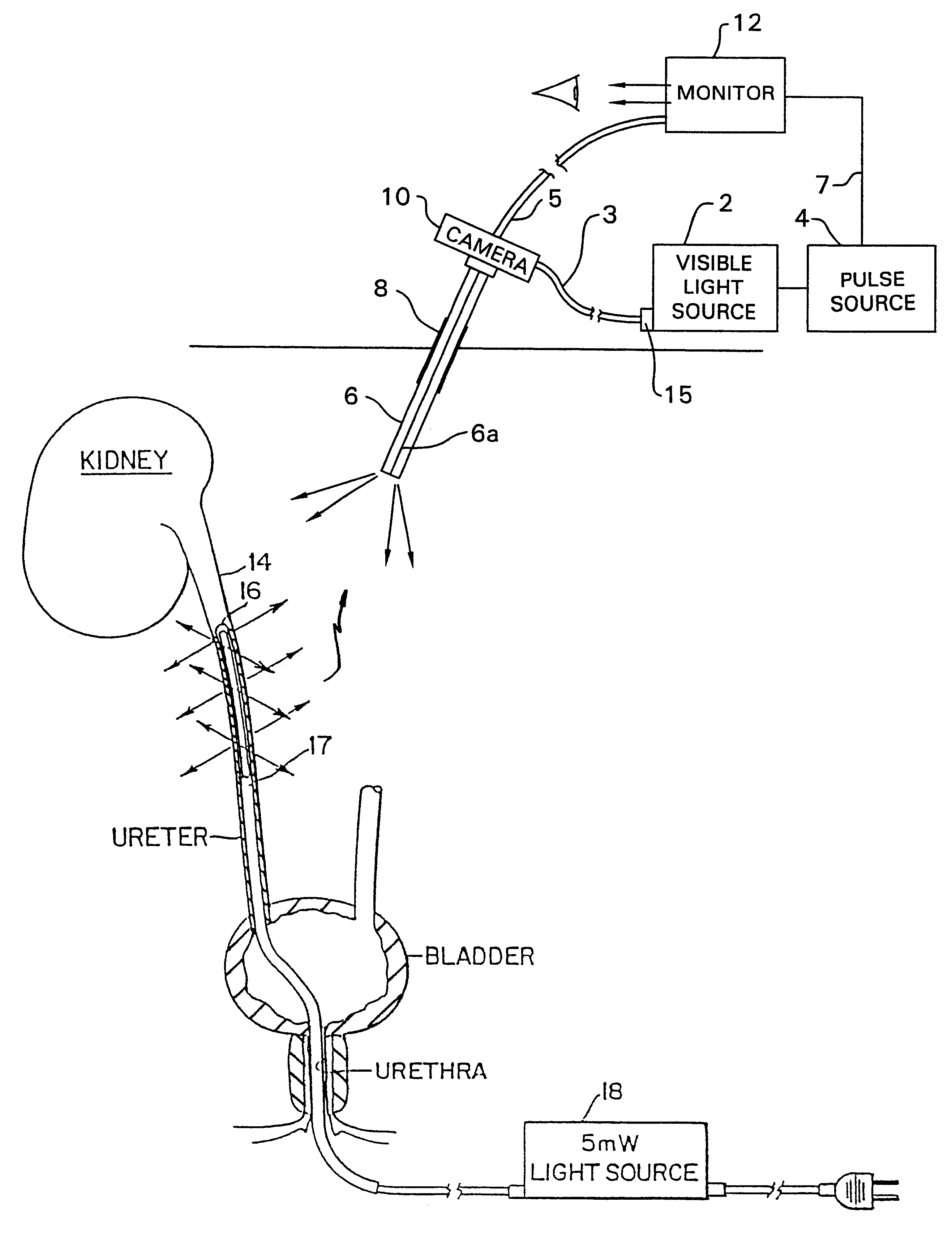
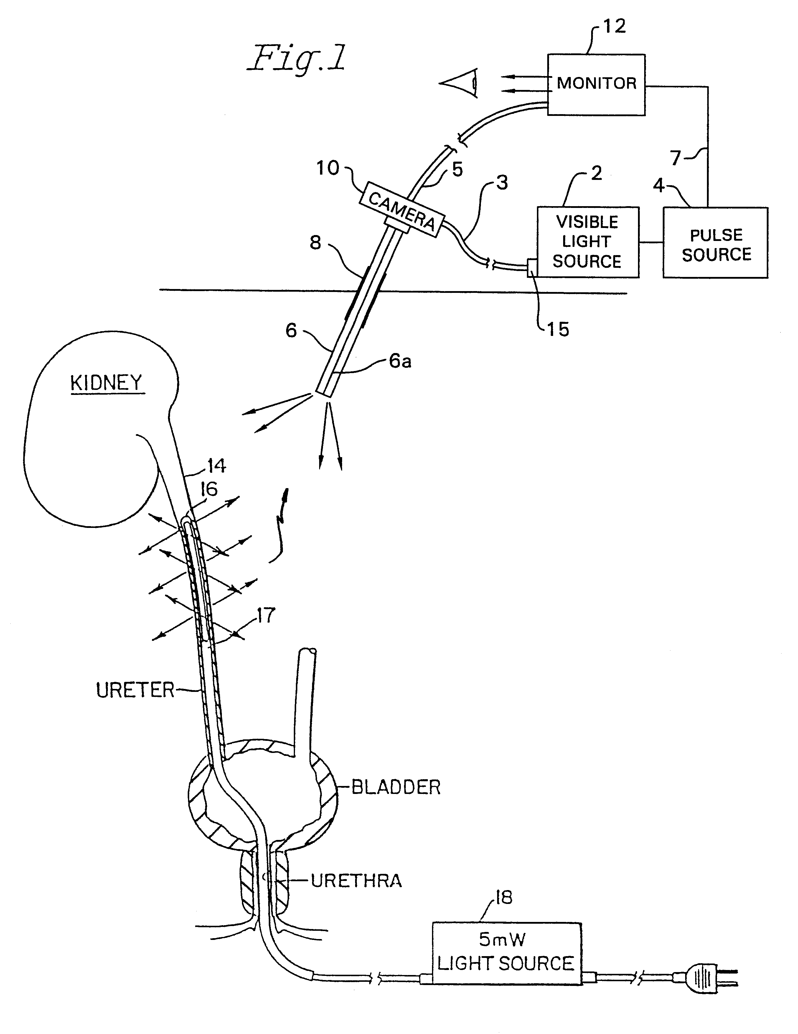
Referring specifically to FIG. 1 of the accompanying drawings, there is illustrated a diagram of a system employing a pulsed laparoscopic visible light source 2. The source 2 is turned on and off by a source of energizing pulses 4 at a rate that is synchronized with the frame rate of a monitor 12 via lead 7.

The endoscope 6 consists of a lens system surrounded by a fiber optic bundle 6a. The light cable 3 couples the endoscopic light source 2 to the fiber optic bundle 6a of the endoscope. During endoscopic procedures, the surgical field is illuminated using the endoscope 6 coupled to the endoscopic light source 2 via the light cable 3. Specifically, the distal end of the endoscope 6 is located internally of a body in a region to be illuminated. The proximal end of the endoscope 6 has an adapter 51 (FIG. 3) that couples the distal end of the light cable 3 to the proximal end of the internal fiber optic bundle 6a of the endoscope 6. The proximal end of the light cable 3 is coupled to t...


PUM


Abstract

An apparatus and method for identifying a body member during a body intrusive procedure includes infrared light energy which is applied to the body member. Substantially visible infrared free light is introduced into the region. The body member is located by detecting the infrared light energy applied thereto. The infrared light energy may be applied to the body member via a light guide which is inserted into or placed in contact with the body member. In addition, a body member to be located may be illuminated from one side and the location of the illuminator detected by a probe on the other side of the body member.

Description

The present invention relates to a method and apparatus for transillumination of various parts of a living body to avoid damaging such parts during an invasive procedure and more specifically to the use of two different light sources in such procedures.Although the present invention is described in connection with protection of a ureter during a surgical procedure, this is done merely for purposes of ease of illustration; the invention being useful for protection of various body parts lying adjacent to a region subjected to an invasive procedure.Currently practiced methods and devices used to transilluminate the ureters to permit ready location and thus protection of the ureter during endoscopic procedures require the cystoscopic placement of a catheter housing and a fiber optic light guide into the lumen of the ureter. The distal portion of the fiber optic light guide is treated to allow light preferably to emit circumferentially from the wall of the fiber. The proximal end of the ...

Claims


Application Information

Patent Timeline
Patent Type & Authority Patents(United States)
IPC IPC(8): A61B5/00A61B1/06A61B1/07A61B1/313A61B19/00
CPCA61B1/3132A61B5/0059A61B5/4528A61B19/40A61B19/5212A61B2019/5206A61B90/04A61B90/361A61B2090/306A61B1/0655
Inventor FONTENOT, MARK G.FEINBERG, RICHARD
Owner STRYKER CORP
Why Eureka
Try Eureka