Optical member with handling portion and method for manufacturing optical member and method for mounting optical member and optical module

Inactive Publication Date: 2006-01-12
LAPIS SEMICON CO LTD
View PDF14 Cites 1 Cited by
  • Summary
  • Abstract
  • Description
  • Claims
  • Application Information

AI Technical Summary

Benefits of technology

[0028] It is preferable that the positioning mark is asymmetrically formed with respect to a virtual plane which includes the optical axis of the luminous flux conversion portion and goes across the handling portion, in order to identify either one of both surfaces of the optical substrate. According to this constitution, if the luminous flux conversion portion is formed on either face of the optical substrate, by making the handling portion asymmetric, it is discriminated with ease with the help of the mark on which face the luminous flux is. On the one hand, even if luminous flux conversion portions having different optical characteristics are respectively formed on the both faces of the optical substrate, it is discriminated also with ease which luminous flux conversion portion is on which fac

Problems solved by technology

Consequently, it would never be easy to handle and correctly arrange such a minute micro-lens in a predetermined position.
Then, even if trying to handle and hold the minute micro-lens by making use of negative pressure, the micro-lens provided with the annular portion has a circular curved surface along the circumference thereof, so that it would not properly wor

Method used


Image

  • Optical member with handling portion and method for manufacturing optical member and method for mounting optical member and optical module
  • Optical member with handling portion and method for manufacturing optical member and method for mounting optical member and optical module
  • Optical member with handling portion and method for manufacturing optical member and method for mounting optical member and optical module

Examples


second embodiment

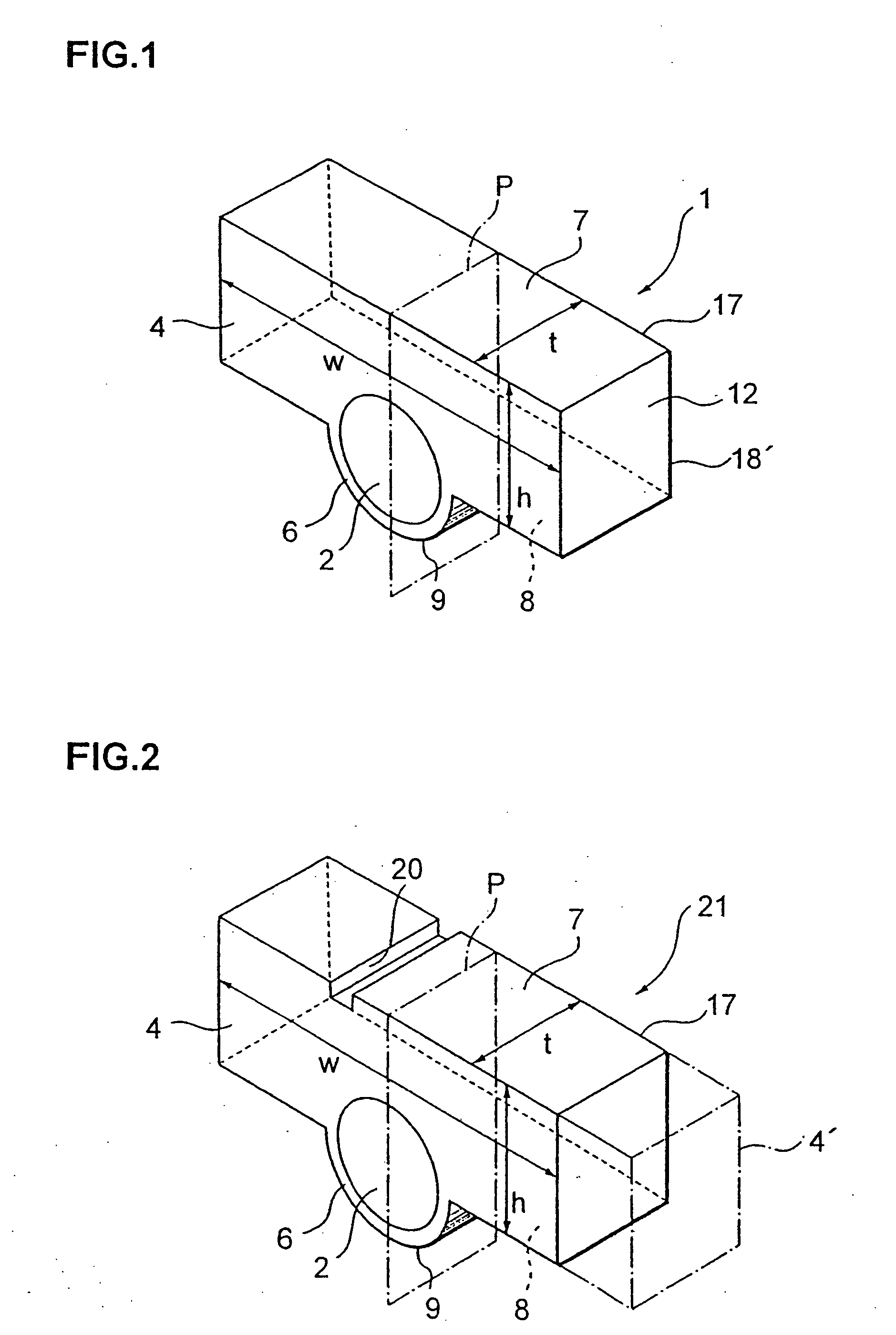
[0108]FIG. 2 is a perspective view showing the constitution of a lens element 21 according to the invention. The lens element 21 has a mark 20 put on the upper flat plane 7 of the handling portion 4, and except for this point, the lens element 21 has the same constitution as the lens element 1. In the example shown in FIG. 2, the mark 20 is made in the form of a groove as put on one side portion of the upper flat plane 7 of the handling portion 4. Being provided with the mark 20 like this, the handling portion 4 comes to be asymmetric with respect to a virtual plane P which passes through the optical axis of the lens portion 2 and is perpendicular to the surface of the lens portion 2 and to the extending direction of the handling portion 4 as well. The lens portion 2 is formed only on one side plane of the optical substrate.

[0109] In FIG. 2, seeing the lens element 21 placed in such a position that the mark 20 comes on the left side of the figure, you would see it with ease, with th...

third embodiment

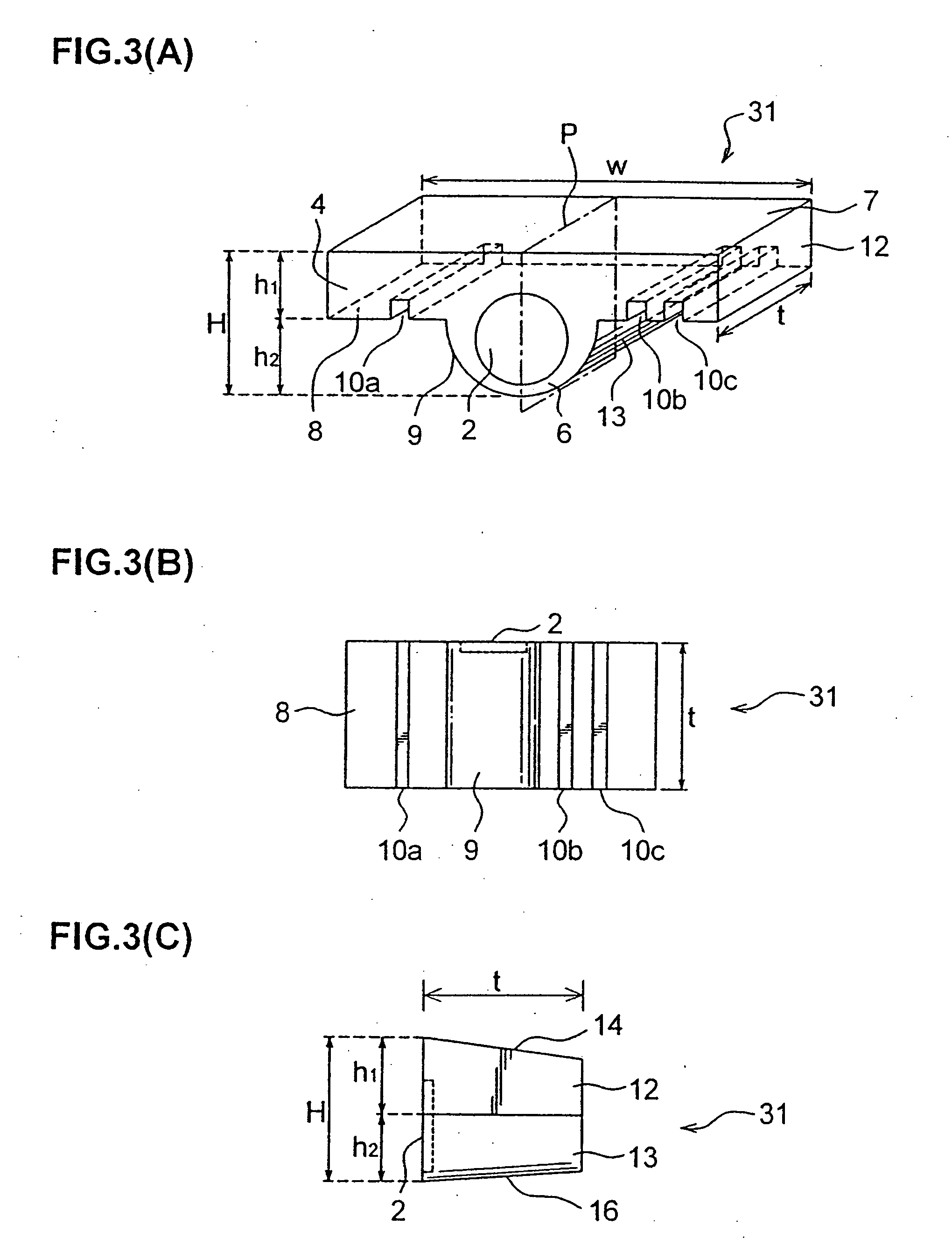
[0114] Constitution of a lens element 31 according to the invention is shown in FIGS. 3A through 3C, wherein FIG. 3A is a perspective view of the lens element 31, FIG. 3B a bottom view of the same, and FIG. 3C a side plan view of the external form of the same, respectively. As will be seen from the above three figures, the lens element 31 is provided with three positioning grooves 10a, 10b, and 10c formed on its bottom plane 8. As shown in FIG. 3C, the height of the lens element 31 is not uniform but slightly varied in the direction of its thickness t. The other constitution is the same as that of the lens element 1.

[0115] Three grooves 10a, 10b, and 10c are formed to open toward the lens formation plane and the opposite plane thereof as well, and to extend from the lens formation plane side to the opposite plane thereof, going across the thickness t of the lens element 31. At least one of three grooves 10a, 10b, and 10c is used for positioning of the lens element 31 when mounting i...

fourth embodiment

[0118]FIG. 4 is a perspective view showing the constitution of a lens element array 41 according to the invention. The lens element array 41 is made up of a plurality of lens elements 1 which are connected in series with one another to form an array extending in one direction. That is, the lens element array 41 is made of the optical substrate and includes a plurality of lens portions 2 arranged to form an array, a plurality of edge portions 6, each of which is located on the lower side of the external circumference of each lens portion 2 and has a circular arc shape lying along the circular circumference of the lens portion 2, and a handling / supporting portion 4a which is formed to connect and integrate all of the lens portions 2. The handling / supporting portion 4a is connected with each lens portions 2 on the other side of the external circumference thereof, extends in the direction of the aligned lens portions 2 on the surface approximately in parallel with the surface of the len...


PUM


Abstract

A lens element 1 is formed by making use of an optical substrate, and includes a lens portion 2, an edge portion 6 in the form of a circular arc provided along the circumference of the lens portion 2, and a handling portion 4 which is integrated with the lens portion 2 and the edge portion 6 as well and extends with a width wider than that of the lens portion 2. The handling portion 4 can be caught and held by chucking vacuum suction and so forth. The lens element 1 can be handled by catching the handling portion 4 without directly touching the lens element 1, and thus the lens element 1 is neither damaged nor contaminated, and stably handled with ease.

Description

[0001] This is a Divisional application of U.S. patent Ser. No. 10 / 854,339, filed May 27, 2004, which is a Divisional application of U.S. patent application Ser. No. 10 / 724,625, filed Dec. 2, 2003, now U.S. Pat. No. 6,798,589, which is a Divisional application of U.S. patent application Ser. No. 10 / 136,326, filed May 2, 2002, now U.S. Pat. No. 6,683,733.BACKGROUND OF THE INVENTION [0002] 1. Field of the Invention [0003] The present invention relates to an optical member such as a lens element preferably applicable to optical communication devices, tools, and systems and more particularly, to an optical member such as a micro-lens suitable for constituting things by means of a microscopic optical element of the diffraction type such as a Computer Generated Holographic (CGH) optical element. The invention also relates to a method for manufacturing the optical member as described above, an optical module, and a method for mounting the optical member as mentioned above. [0004] 2. Prior ...

Claims


Application Information

Patent Timeline
IPC IPC(8): G02B7/02G02B3/00G02B5/32G02B6/12G02B6/124G02B6/32G02B6/36G02B6/42
CPCG02B3/00G02B2006/12102G02B3/005G02B3/0075G02B5/32G02B6/1245G02B6/32G02B6/327G02B6/362G02B6/3636G02B6/3652G02B6/3676G02B6/3692G02B6/4204G02B6/4206G02B6/4207G02B6/4221G02B6/4224G02B6/423G02B6/4239G02B6/4249G02B7/02G02B7/021G02B7/022G02B3/0012
Inventor UEKAWA, MASAHIROKOTANI, KYOKOSASAKI, HIRONORITAKAMORI, TAKESHIMAENO, YOSHINORI
Owner LAPIS SEMICON CO LTD
Why Eureka
Try Eureka