Safety Needle

a safety needle and accessory technology, applied in the field of safety needle accessories, can solve the problems of low flow rate, easy access to the needle tip, and low flow rate of the end of the sleeve, and achieve the effect of preventing the foaming of medicaments, preventing easy access to the needle tip, and reducing the flow ra

Active Publication Date: 2009-01-08
SALVUS TECH LTD
View PDF6 Cites 41 Cited by
  • Summary
  • Abstract
  • Description
  • Claims
  • Application Information

AI Technical Summary

Benefits of technology

[0006]This safety needle accessory protects the user from needle stick injuries while still allowing the sharp end of the needle to be exposed for filing the syringe with the injectate from a vial or other appropriate container prior to performing the injection. The present invention also provides a device comprising the accessory described herein and an injection device (e.g. a syringe), as well as a method for preparing an injection comprising the steps of providing the device, removing the cap, and filling the injection device with an injectate from a suitable container. The present invention further provides a method for injecting a patient using the device as defined above.

Problems solved by technology

Generally, these devices employ a sliding sleeve which is biased towards the sharp tip of the needle, so that after use, the end of the sleeve prevents easy access to the needle tip.
The reasons are that the rubber seal on the vial from which the medicament is withdrawn may have surface contamination, or a piece of the rubber seal may partially block the needle (“coring”), and the small needles used for many injections have a low flow rate, which, during filling, can cause foaming of the medicament.
However, even in the most assiduous of healthcare practices, frequently the same needle is used to fill the syringe and to inject the patient.
A problem arises with safety needles however, particularly with the preferred passive type.
The only solution would be to replace the used needle with a new one—which could be considered too expensive and time consuming.

Method used


Image

  • Safety Needle
  • Safety Needle
  • Safety Needle

Examples


Embodiment Construction

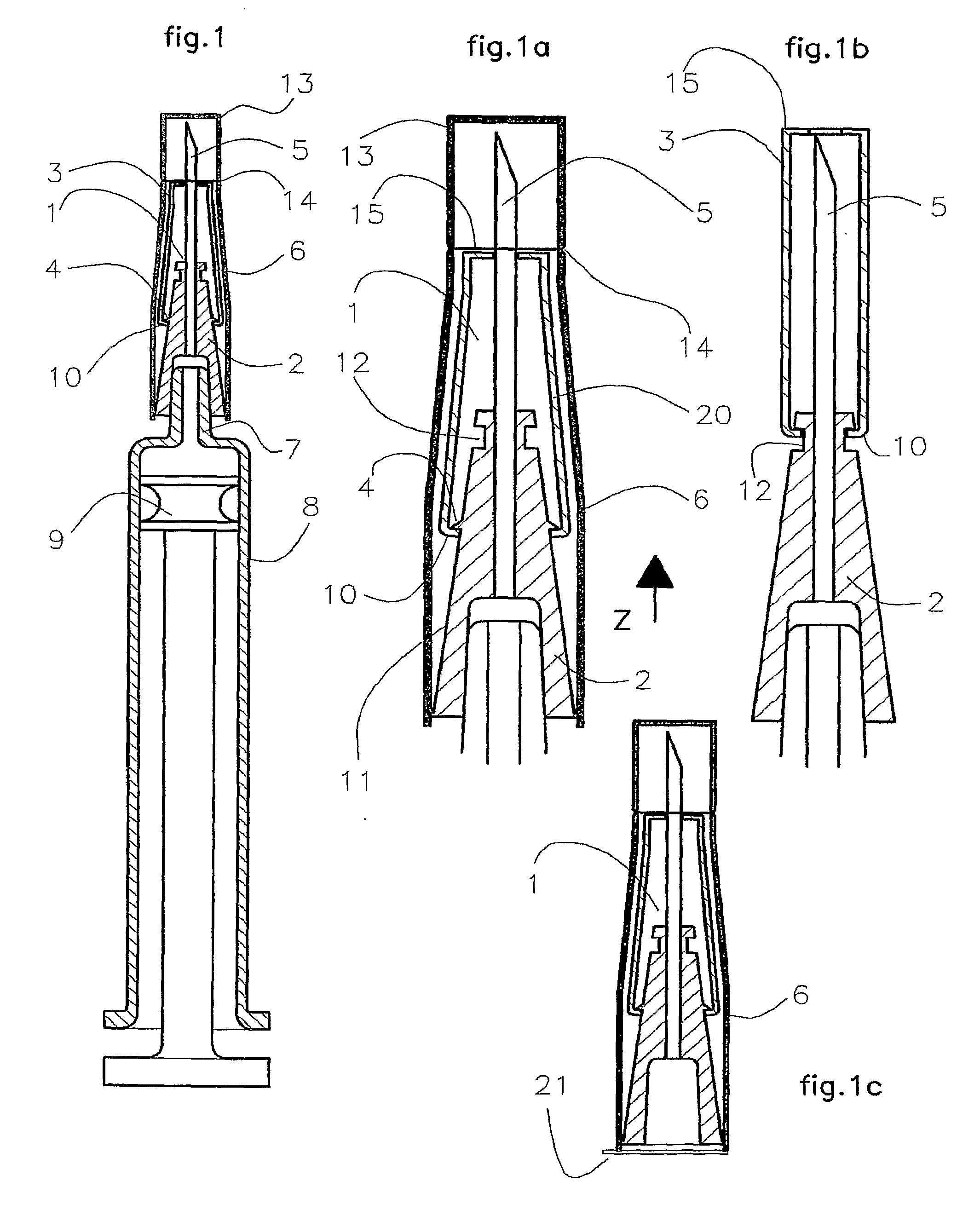
[0015]In the drawings, like parts are given the same reference numerals.

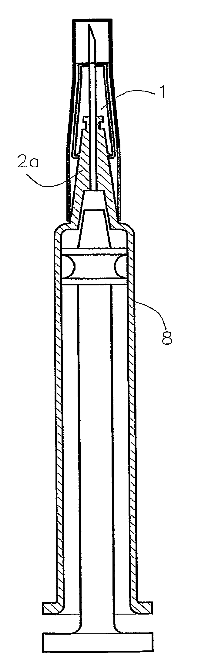
[0016]The present invention provides a means of overcoming the problem of filling a syringe when using some types of passive safety needle. The following descriptions are based on the use of the safety needle disclosed in WO 2004 / 071560 but are applicable to many other safety needles which use a biased sliding sleeve that covers the needle after use and locks.

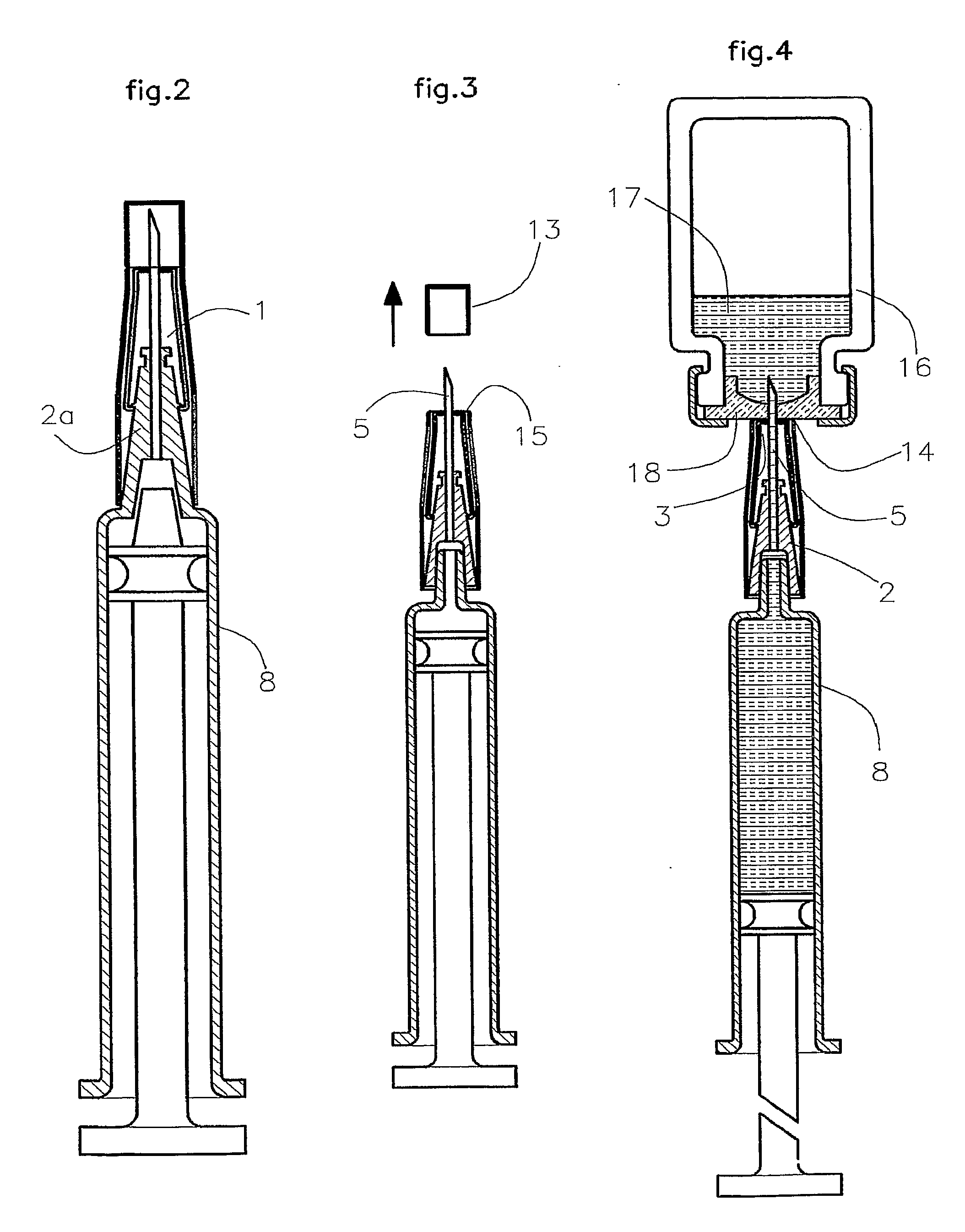
[0017]The present invention makes use of the packaging to provide blocking means to prevent the sleeve moving during filling. The packing is removed after filling, and the safety needle is used in the normal way. It is common to supply needles in a stiff tubular pack, which is used to hold the needle safely when fitting it to the syringe. The pack is then removed by pulling it off in an axial direction. Thus the present invention does not add to the cost of the needle, but does provide additional benefit.

[0018]The needle packed within a stiff protective pac...


PUM


Abstract

This invention relates to a safety needle to prevent needle stick injuries. The invention provides a safety needle accessory comprising a hollow needle having a base end and a sharp end, a hub surrounding the base end of the needle and having a connector for connection to an injection device, a sleeve surrounding the hub and slidable relative to the hub in an axial direction, an elastically deformable member, and a pack having a closed end covering the sharp end of the needle and an open end exposing the connector of the hub and which is releasably mounted over the needle, hub and sleeve. The sleeve is slidable in a first axial direction from a first position in which the needle is fully or partially covered by the sleeve to a second position in which the needle is exposed, via an intermediate position between the first and second positions in which the sharp end of the needle projects from the sleeve, and in a second axial direction from the second position to a third position in which the needle is fully covered by the sleeve. The deformable member is deformed by the sleeve sliding from the first to the second position and the force for sliding from the second to the third position is provided by the stored elastic energy in the deformable member. The closed end of the pack has a removable cap at a position on the pack such that removal of the cap exposes the sharp end of the needle but not the sleeve when the sleeve is in the intermediate position.

Description

CROSS-REFERENCE TO RELATED APPLICATIONS[0001]This application is a Section 371 of International Application No. PCT / US2007 / 060316, filed Jan. 10, 2007, which was published in the English language on Jul. 19, 2007, under International Publication No. WO 2007 / 082226 A1 and the disclosure of which is incorporated herein by reference.BACKGROUND OF THE INVENTION[0002]This invention relates to a safety needle accessory and in particular to safety needle accessory incorporating a protective pack. Safe hypodermic needles reduce the risk of needle stick injuries, and are increasingly specified in many healthcare areas as a means of reducing cross-infection with serious diseases. Generally, these devices employ a sliding sleeve which is biased towards the sharp tip of the needle, so that after use, the end of the sleeve prevents easy access to the needle tip. The sleeve may be operated manually, so-called “active” safety needles, or automatically, known as “passive” safety needles. Passive ne...

Claims


Application Information

Patent Timeline
Patent Type & Authority Applications(United States)
IPC IPC(8): A61M5/32
CPCA61M5/002A61M5/3213A61M2005/3268A61M2005/312A61M2005/3247A61M5/326
Inventor WESTON, TERENCE EDWARD
Owner SALVUS TECH LTD
Why Eureka
Try Eureka