Medical Device with Sliding Frontal Attachment and Retractable Needle
Active Publication Date: 2014-01-09
RETRACTABLE TECH INC
View PDF13 Cites 34 Cited by
Summary
Abstract
Description
Claims
Application Information
AI Technical Summary
This helps you quickly interpret patents by identifying the three key elements:
Problems solved by technology
Method used
Benefits of technology
[0025]The frontal attachment of the invention can also be used with needles and syringes of different and varying gauges and sizes without special modification. If desired, either the associated medical apparatus with which the subject medical device is used, or the medical itself, can be provided with a plug containing an anticoagulant such as heparin to use in blood gas applications. The structure and operation of the invention are simplified by the provision of a substantially linear fluid flow path and a needle retraction chamber and associated retraction cavity that are offset laterally from the fluid flow path during fluid injection or extraction. The subject medical device has few parts, and those are easily and inexpensively molded.
[0026]The medical device of the invention also embodies safety features that are not typically available in many prior art devices. For e
Problems solved by technology
The luer tips of such syringes are typically exposed to bacterial or viral contamination by incidental contact with a person or object during use.
Use of such moveable gu
Method used
Image
Click on the blue label to locate the original text in one second.
Reading with bidirectional positioning of images and text.
Examples
Embodiment Construction
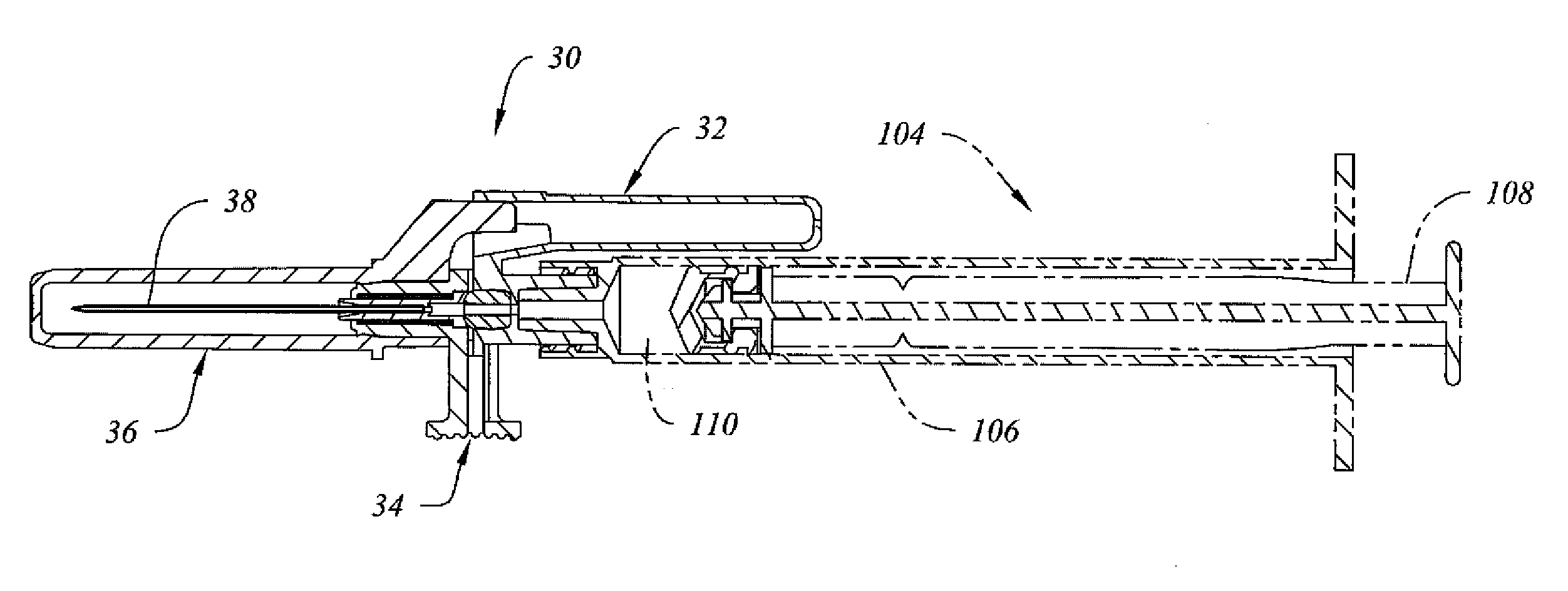
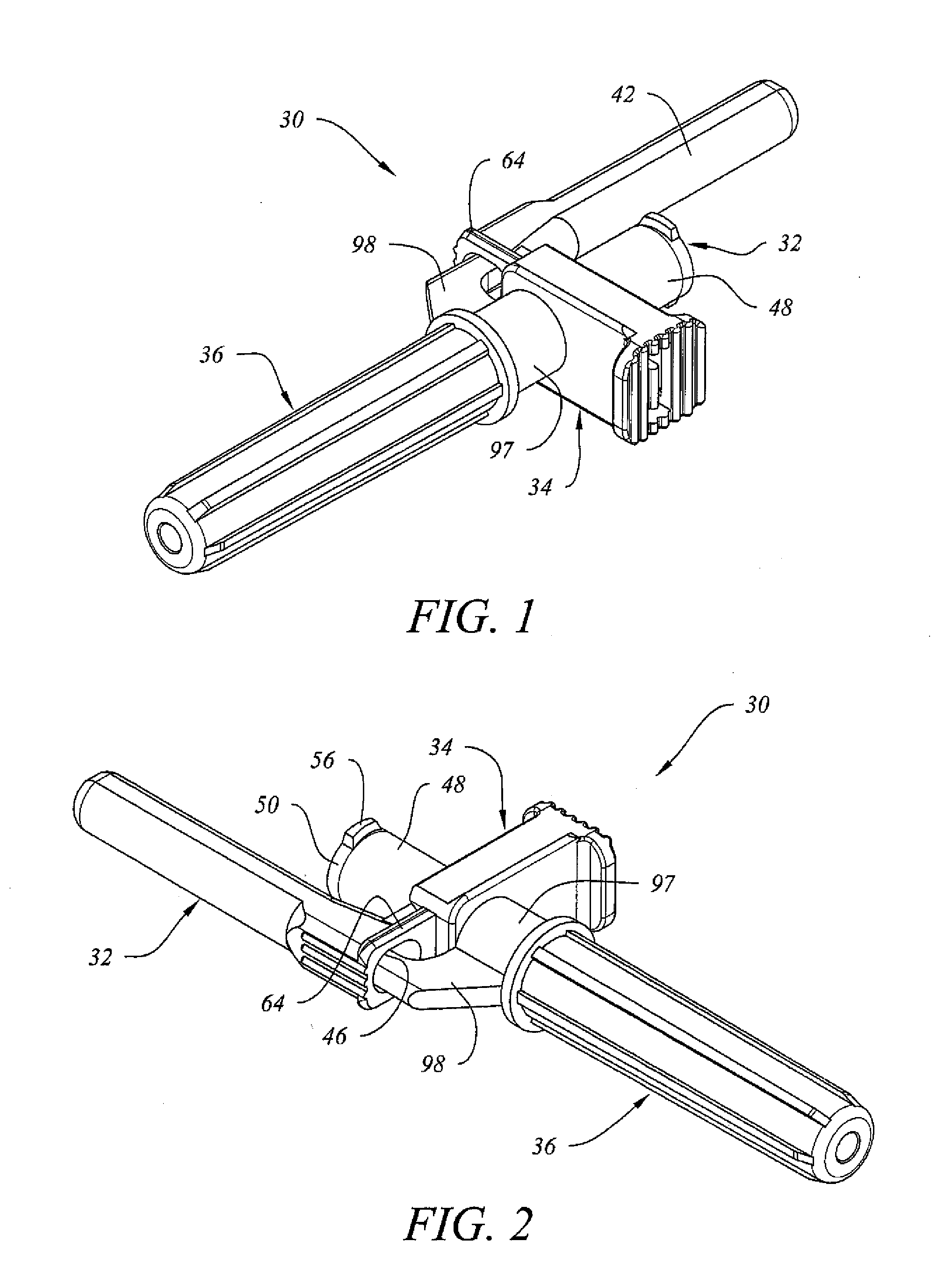
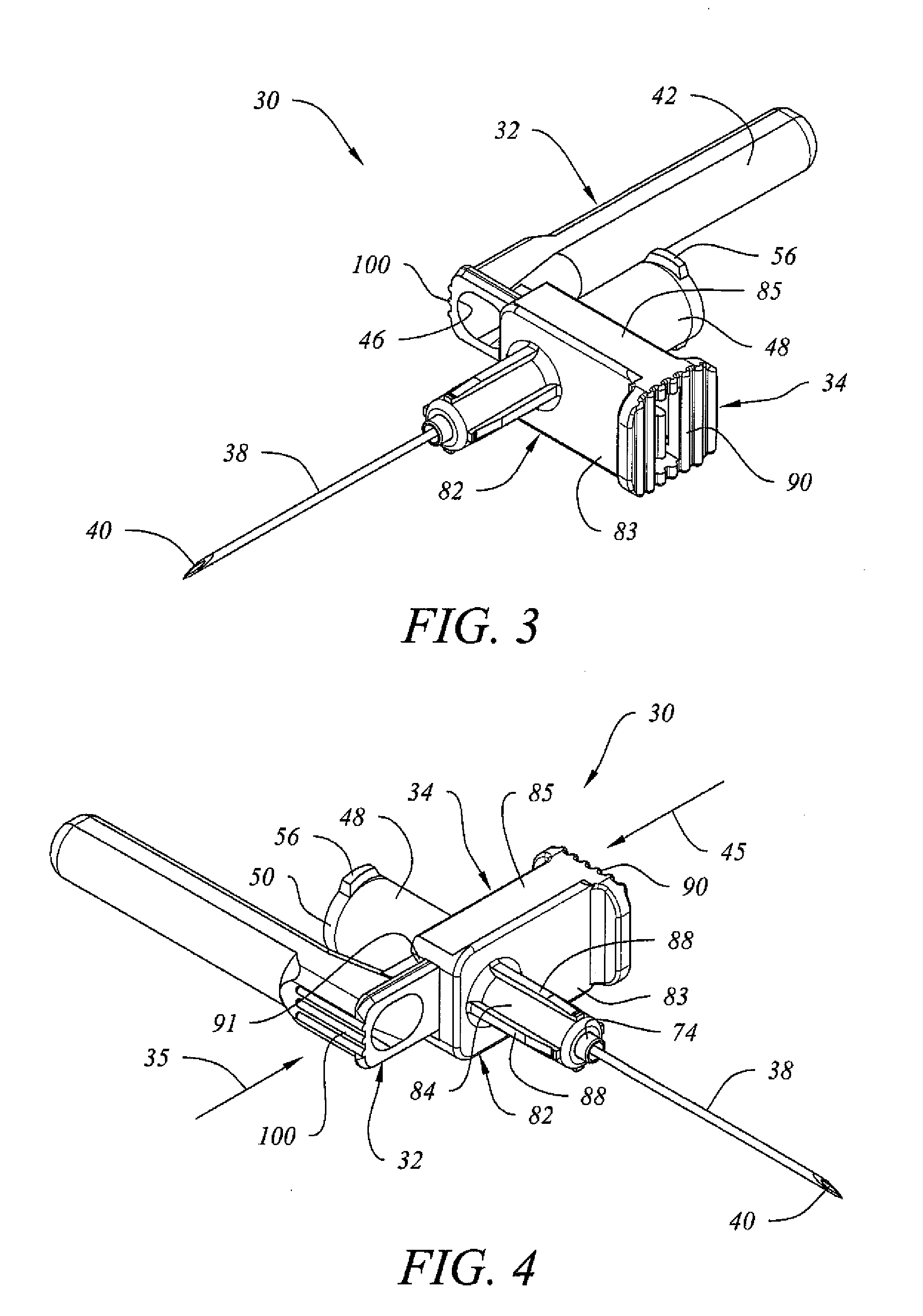
[0073]Referring to FIGS. 1, 2 and 10, medical device 30 comprises connector housing 32, frontal attachment 34 and locking needle cover 36. Referring to FIGS. 3, 4 and 9, locking needle cover 36 is removed to reveal needle 38 with upwardly facing beveled tip 40. Referring to FIGS. 5 and 9, connector housing 32 of medical device 30 desirably further comprises needle retraction chamber 42 having rearwardly facing closed end 44 and forwardly facing opening 46 bounding retraction cavity 58. Opening 46 is desirably elongated or oval shaped, with a transverse dimension greater than the inside diameter of the elongate cylindrical portion of needle retraction chamber 42. As seen in FIGS. 5-8, opening 46 desirably transitions along tapered inside wall 102 (back 103 visible in FIG. 8) to the inside diameter of needle retraction chamber 42. Tapered inside wall 102 facilitates insertion and removal of locking arm 98 of locking needle cover 36, and also facilitates the entry of needle holder 72 a...
PUM
Abstract
A medical device having a frontal attachment and a connector housing having or attachable to an associated medical apparatus, the frontal attachment slidably engaging the connector housing and having a forwardly projecting, rearwardly biased needle and a needle retraction assembly, and the connector housing having a needle retraction cavity laterally offset from the needle in a first position, the needle retraction cavity being selectively movable relative to the frontal attachment following use to reposition the needle retraction cavity into alignment with the needle to permit retraction.
Description
CROSS-REFERENCE TO RELATED APPLICATIONS[0001]This application claims the benefit of the earlier filing dates of U.S. Provisional Patent Applications Nos. 61 / 737,263 filed Dec. 14, 2012, and 61 / 836,723 filed Jun. 19, 2013. This application is also a continuation-in-part of non-provisional U.S. patent applications Ser. Nos. 13 / 714,819 filed Dec. 14, 2012, now pending; 13 / 841,462, filed Mar. 15, 2013, now pending; and 13 / 842,000, filed Mar. 15, 2013, now pending, from which priority is claimed. This application is also a continuation-in-part of U.S. application Ser. No. 13 / 902,564, filed May 24, 2013, now pending, which is a division of application Ser. No. 13 / 470,855, filed May 14, 2012, issued Jun. 25, 2013 as U.S. Pat. No. 8,469,927, which is a continuation of application Ser. No. 12 / 136,462, filed Jun. 10, 2008, now abandoned, from which priority is also claimed.BACKGROUND OF THE INVENTION[0002]1. Field of the Invention[0003]This invention is a medical device having a frontal attac...
Claims
Application Information
Patent Timeline
Application Date:The date an application was filed.
Publication Date:The date a patent or application was officially published.
First Publication Date:The earliest publication date of a patent with the same application number.
Issue Date:Publication date of the patent grant document.
PCT Entry Date:The Entry date of PCT National Phase.
Estimated Expiry Date:The statutory expiry date of a patent right according to the Patent Law, and it is the longest term of protection that the patent right can achieve without the termination of the patent right due to other reasons(Term extension factor has been taken into account ).
Invalid Date:Actual expiry date is based on effective date or publication date of legal transaction data of invalid patent.