Wall mounted tool holder

a tool holder and wall mount technology, applied in the field of wall mount holder, can solve the problems of increasing the exterior size of the cleaner, reducing the thickness of the cleaner, and reducing the use efficiency of the cleaner, so as to reduce the thickness, reduce the thickness, and improve the use efficiency.

Inactive Publication Date: 2006-09-05
SHOP VAC
View PDF18 Cites 3 Cited by
  • Summary
  • Abstract
  • Description
  • Claims
  • Application Information

AI Technical Summary

Benefits of technology

[0010]The invention is a wall mounted tool holder adapted to be mounted on a flat wall or an unfinished wall with exposed studs to hold vacuum cleaner tools of different types and sizes and accompanying vacuum cleaner hoses. The holder can be made from a flat injection-molded preform made from thermo-plastic with reduced thickness hinges and break away pieces attached to a central panel. The holder can be easily and inexpensively molded. The flat pre-form is efficiently stacked permitting inexpensive packaging, transport and pre-sale display.
[0012]The holder has a central panel that can be flexed when mounted on a wall or between studs. This flexibility allows the panel to bow away from the wall or studs and permit mounting of the holder between studs not spaced apart an exact distance. Tools are held behind the bowed panel.
[0014]The tool holder of the present invention allows a user to store vacuum cleaner tools of different diameters and any hoses used with the vacuum cleaner. There is no need for multiple holders that are each dedicated to hold accessories of one diameter.
[0015]The tool holder can be easily mounted on either a flat wall or a wall having exposed studs in a location convenient to their use. This facilities tool organization and eases cleaning tasks.

Problems solved by technology

Storage of vacuum cleaner hoses and tools is difficult.
Tools attached to a vacuum cleaner body complicate use of the cleaner by increasing the exterior size of the cleaner.
The tools can become dislodged during use of the cleaner and can obstruct access to the body when changing the refuse receptacle or servicing the vacuum.
The racks are large, expensive and complicated to produce and assemble.
Often, conventional racks are not designed to accept specialized tools of different sizes and types.
There is additional difficulty when vacuum cleaner tools and hoses are stored in rooms with unfinished walls having exposed studs, such as closets, basements or garages.
These rooms lack a continuous flat mounting surface.
Conventional wall racks are difficult to mount on walls with exposed studs and do not make efficient use of available space between studs.

Method used


Image

  • Wall mounted tool holder
  • Wall mounted tool holder
  • Wall mounted tool holder

Examples


first embodiment

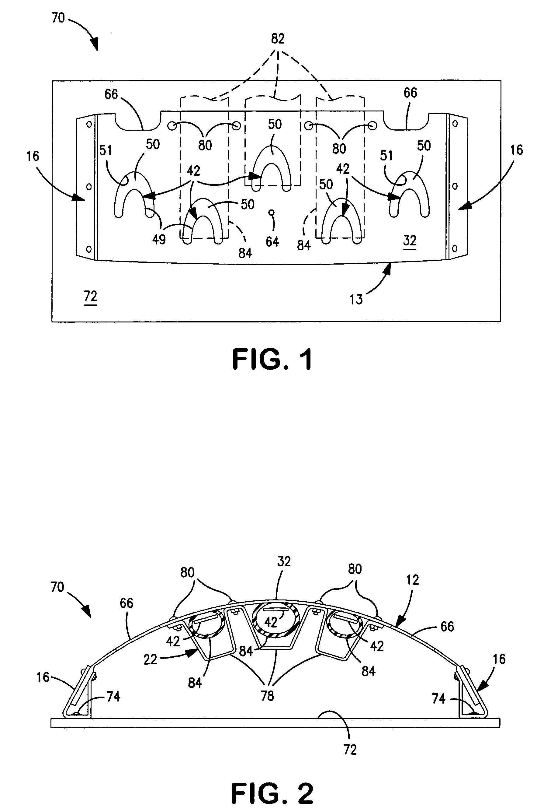
[0037]FIGS. 1, 2 and 3 illustrate a first embodiment tool holder 70 mounted on a vertical flat or finished wall 72. Holder 70 includes a body 13 and two support preforms 16, previously described. Body 13 is identical to body 12 but without outer hinges 36 or mounting panels 40.

[0038]The holder is mounted on the wall 72 by mounting both support preforms 16 on the wall with hinges 60 extending vertically. The mounting panels 56 are then attached to the wall 72 by appropriate fasteners 74 extending through openings 64 in the vertically oriented mounting panels 56. The two mounting panels 56 are spaced apart a predetermined distance so that panel 32 is bowed out from wall 72 as illustrated.

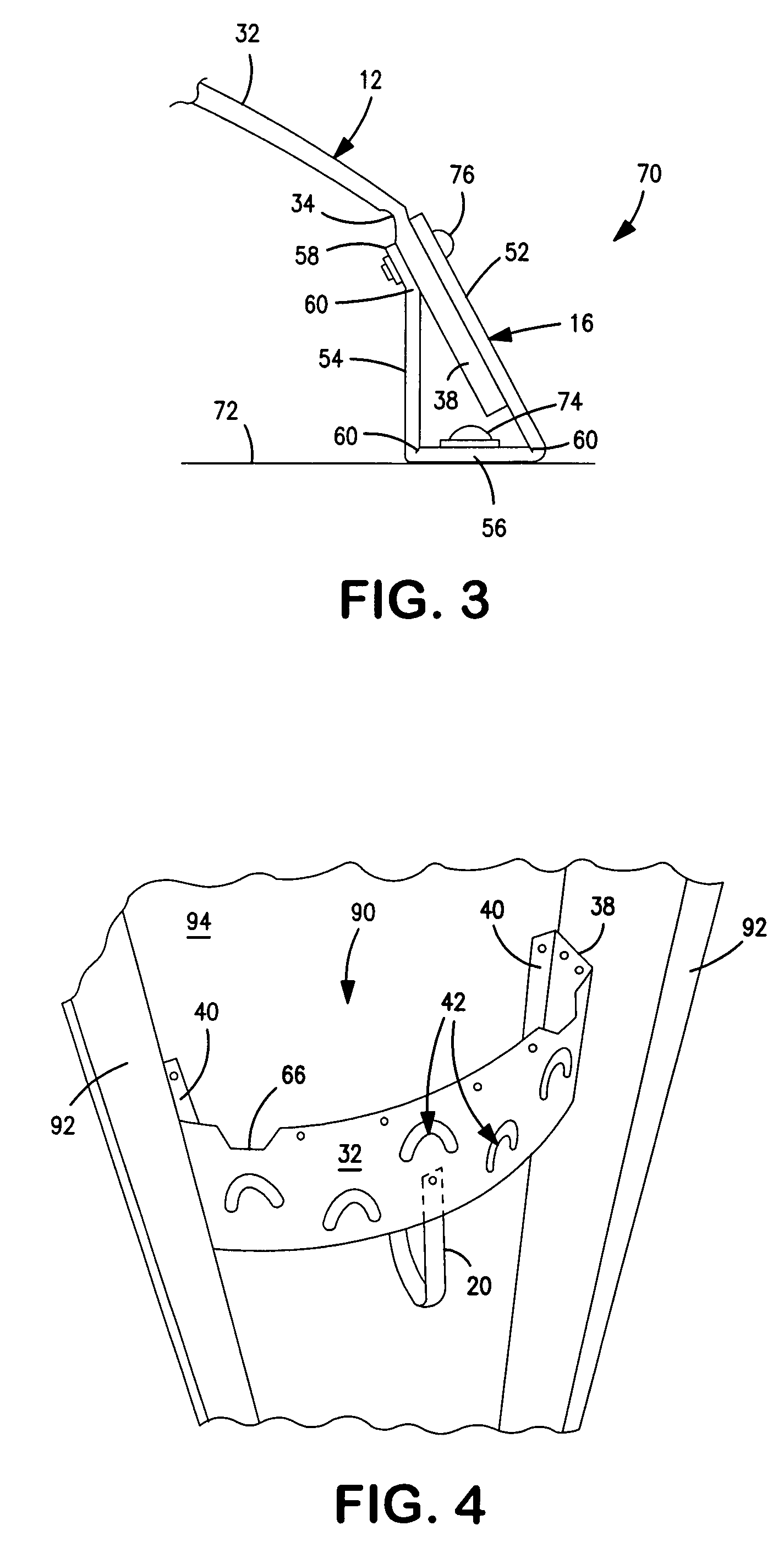
[0039]One of the panels 38 of body 13 is positioned adjacent the mounting panel 56 of one support preform and the support preform panels 52 and 54 are bent about hinges 60 away from wall 72 to capture or sandwich panel 38 between panels 52 and 54 as shown in FIG. 3. The attachment panel 58 is bent out...

second embodiment

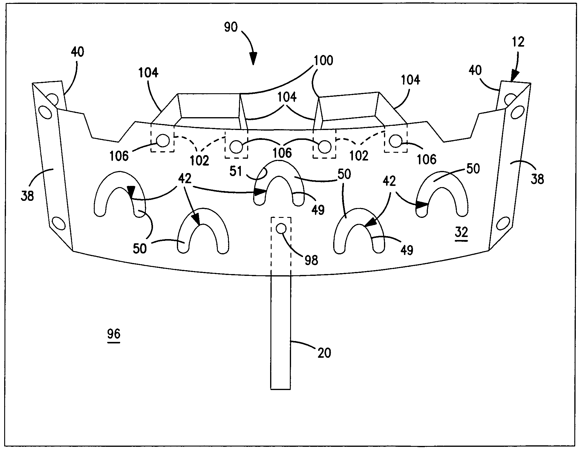
[0045]If desired, strap 20 may be formed into a loop and secured to the inner surface of panel 32 at mounting hole 64 located below central finger 42. Strap 20 forms a loop for supporting a coiled vacuum cleaner hose, as shown more clearly in FIGS. 4, 5 and 6. The strap extends straight down from hole 64 and bends inwardly from the panel to form a hose support loop 89 located on the convex side of the panel, between the panel and the adjacent wall. Loop 89 supports the hose behind the panel. The hose does not extend out from the panel. Hinge 91 on the inner end of the loop is flexed to locate loop 89 inside the panel.

[0046]Second embodiment tool holder 90 is illustrated in FIGS. 4–8. As shown in FIG. 4, holder 90 may be mounted between two vertical studs 92 extending to one side from unfinished wall 94. Alternatively, holder 90 may be mounted on flat finished wall 96 as shown in FIG. 5.

[0047]Holder 90 includes body 12 with a finger or central panel 32 and mounting panels 38 and 40 t...

third embodiment

[0055]FIG. 12 illustrates a third embodiment tool holder 140 which is similar to holder 14 shown in FIG. 11. Holder 140 includes a central panel 142, like panel 32, and five tool retention fingers 144 and surrounding slots 146 having the same shape as fingers 42 and slots 50. The central finger 144 and surrounding slot 146 are identical to the finger 48 and slot 50 in the center of panel 32 with the lower ends of the slot and the base of the finger located on a horizontal line 148 parallel to the top and bottom edges 150 and 152. The fingers and slots to either side of the central finger 144 and slot 146 are tilted away from the central finger and slot proportional to the distance from the central finger and slot so that the finger bases and the lower ends of the slots lie on lines 154 and 156 with the inner end of the slot and finger base located above the outer end of the slot and finger base. The outward tilt of the outer fingers and slots is shown in FIG. 12. The outer fingers 1...


PUM


Abstract

A holder for vacuum cleaner tools includes a flat plastic body mounted on a wall or between exposed studs on a wall with a panel bowed outwardly from the wall. The panel has a plurality of upwardly extending fingers to receive and hold vacuum cleaner tools.

Description

FIELD OF THE INVENTION[0001]The invention relates to a wall-mounted holder for vacuum cleaner tools and the like.DESCRIPTION OF THE PRIOR ART[0002]Vacuum cleaners are common household, shop, and outdoor tools. Many vacuum cleaners have a body containing an air pump and a depository for debris. The body is connected to a hose used to draw air and debris into the machine. Specialized cleaning tools are attached to the free end of the hose, such as brushes, crevice tools, and rug cleaners to facilitate cleaning tasks.[0003]The hoses come in a variety of sizes, commonly from 1.25 inches to 2.5 inches in diameter. Some hoses are measured in metric units. Smaller diameter hoses are preferred for collecting liquid debris and interior house cleaning, while larger diameter hoses are useful for collecting larger debris found in a workshop or outdoors.[0004]The specialized cleaning tools attached to a hose must match the diameter of the hose. Vacuum cleaners that use hoses of different diamete...

Claims


Application Information

Patent Timeline
Patent Type & Authority Patents(United States)
IPC IPC(8): A47F7/00A47L9/00A47L13/51
CPCA47L13/51A47L9/0063A47L9/248
Inventor BERFIELD, ROBERT C.
Owner SHOP VAC
Why Eureka
Try Eureka