Wireless communication accessory for a mobile device

a mobile device and accessory technology, applied in the field of accessories for mobile devices, can solve the problems of shortening the time between charges, affecting affecting so as to increase the longevity of mobile devices, reduce the number of peripherals, and extend the functionality and/or capabilities of mobile devices

Active Publication Date: 2014-03-06
MOPHIE
View PDF9 Cites 160 Cited by
  • Summary
  • Abstract
  • Description
  • Claims
  • Application Information

AI Technical Summary

Benefits of technology

[0008]Certain embodiments disclosed herein relate to mobile device accessories that extend the functionality and / or capabilities of mobile devices. For example, by supplying an external accessory containing an additional battery, more powerful devices and applications can be designed and used without the concern of regular power loss. The additional battery can be contained in an external case and can be electrically coupled through a wire or mounting system, but the additional battery can also be contained inside of another frequently used peripheral—a protective case. By incorporating an additional battery inside of a protective case for the mobile device, a user can reduce the number of peripherals to be carried at any one time and greatly increase the longevity of his or her mobile device by adding a little bit of extra thickness.
[0010]In some embodiments, a mobile device peripheral for a mobile communication device is disclosed, comprising: a protective case and a repeater antenna. In some embodiments, the repeater antenna can be enclosed inside of the protective case. The repeater antenna can either include one or more passive antennas and / or one or more active antennas. In some embodiments, the repeater antenna comprises a first antenna electrically connected to a second antenna. Both antennas can be contained in one device, but the two antennas can also be located in separate peripherals that are capable of electrical coupling. The second antenna can transmit a signal received by the first antenna and vice versa. The second antenna can repeat (or re-transmit) a signal transmitted by the mobile device. In some embodiments, there can be one or more ferrite layers between the first antenna and the second antenna. The ferrite layers can be directly attached to one or both of the antennas (e.g., by adhesive sheets). The ferrite layers can block interference between the two antennas. Additionally the ferrite layers can increase the apparent magnetic depth of an antenna (e.g., a thin antenna), for example if the antenna is used as an inductor to induce a magnetic field from an electrical signal or to induce an electric signal from a magnetic field. In some embodiments, one or more insulating layers can be disposed between the first antenna and the second antenna. For example, there can be an insulating layer attached to the ferrite layer for one or both of the antennas. The insulating layer can be made of a thermoplastic such as Polyethylene Terephthalate; however other insulators may also be used. The ferrite layer can be made of Manganese-Zinc (Mn—Zn), sodium iron oxide (Na—Fe—O2), or some other ferrite material. The antenna can be simply and cheaply constructed using a flexible printed circuit (FPC).

Problems solved by technology

Many mobile devices (e.g., mobile phones, digital assistants, mobile communication devices, handheld computing devices, personal music / video / content players and storage devices) contain expensive, fragile equipment such as breakable glass touchscreens and lenses, easily scuffed decorative finishes, delicate internal electronic components, and easily broken or lost buttons or switches.
As more powerful mobile devices are designed and advanced apps (Geo-location, streaming video, device pairing, etc.) consume more and more power, the limited internal batteries face a losing battle, thereby shortening the time between charges, which limits the usefulness of a mobile device as a user is forced to locate a power source to recharge the battery source and wait until it is recharged.
For instance, such mobile devices may have somewhat limited processing capabilities (e.g., to extend battery power) and limited input / output capabilities.
Some of these telecommunications standards, especially those with lower frequencies, have such a short effective range such that the thickness of a standard mobile device protective case could substantially dampen or interfere with the communication.
With such a short maximum detection and communication range, a mobile device case can severely limit or completely block the mobile device antenna that is used to transmit and / or receive NFC signals.
For example, the thickness of the case can impede the NFC antenna on the mobile device from coming into close enough proximity to receive and / or send NFC data.
Also, the material of the case can interfere with, or otherwise impede, the NFC signal.

Method used


Image

  • Wireless communication accessory for a mobile device
  • Wireless communication accessory for a mobile device
  • Wireless communication accessory for a mobile device

Examples


first embodiment

of Battery Pack

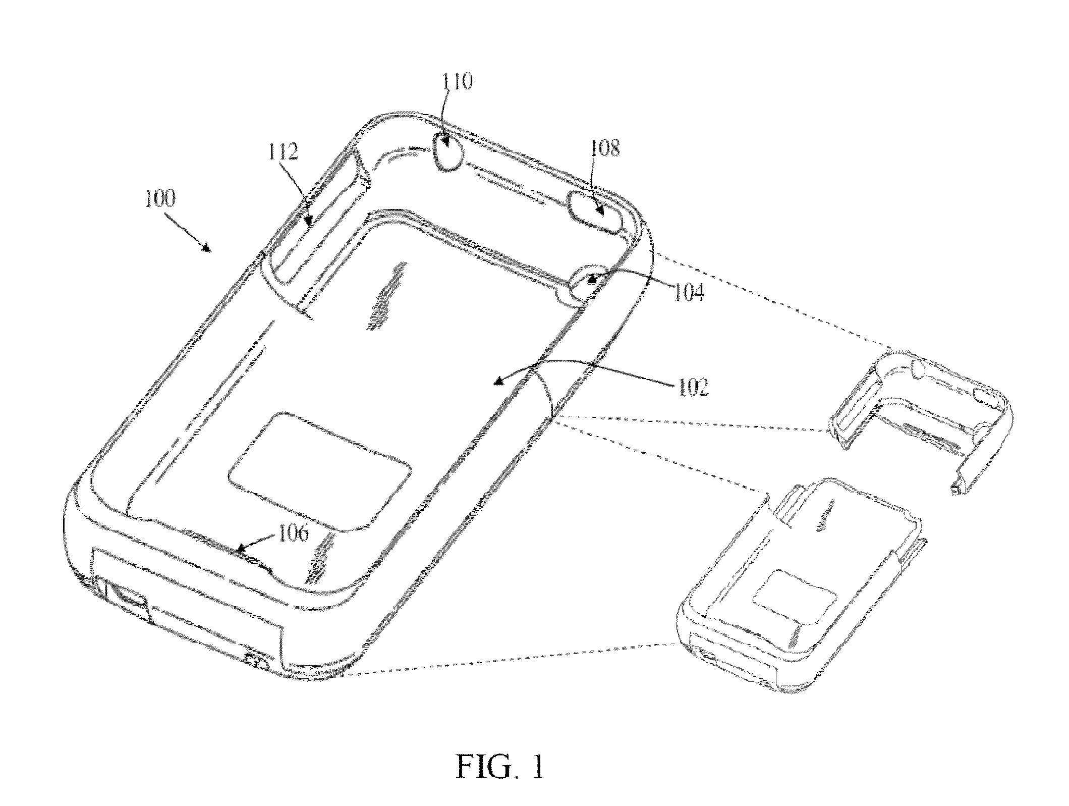
[0107]FIG. 1 illustrates a perspective view of a battery pack for a mobile device according to one example. In this example, the battery pack 100 is shaped to receive or house a mobile phone within a contoured cavity 102. The battery pack 100 has an integrated rechargeable power cell capable of providing power to operate and / or recharge a mobile device mobile device. For illustrative purposes, mobile device is depicted as the mobile communication device sold under the trademark iPhone by Apple Inc.; it is understood by those familiar with the art that other mobile devices such as computers, mobile phones, media players, music players, personal digital assistants (PDAs), tablet computers, and the like may be equally applicable.

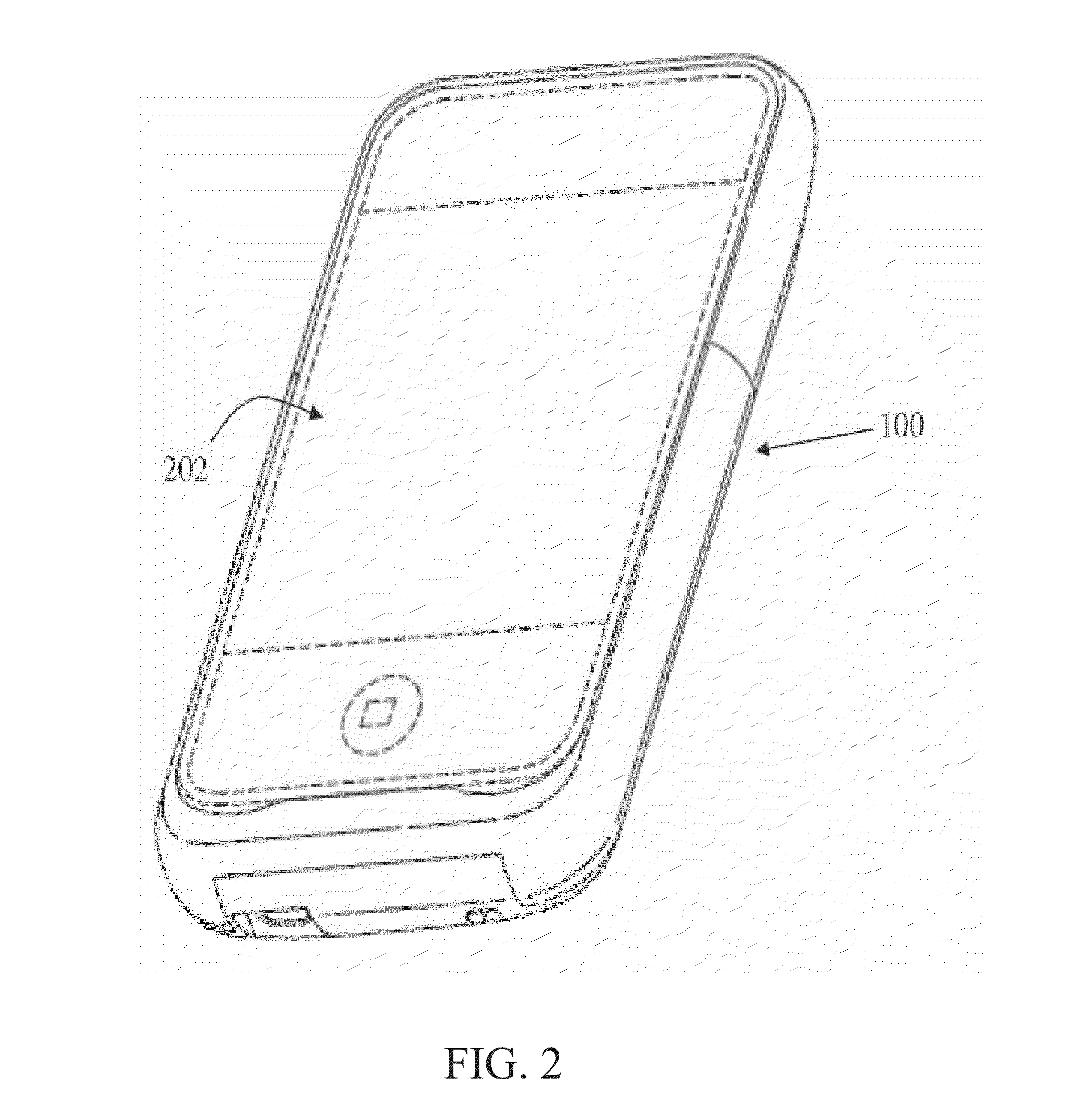
[0108]FIG. 2 illustrates how a mobile device can be housed within the battery pack 100 of FIG. 1. As can be appreciated from this figure, the battery pack 100 is shaped to closely wrap around the mobile device 202 and serves as a protective case ...

second embodiment

of Battery Pack

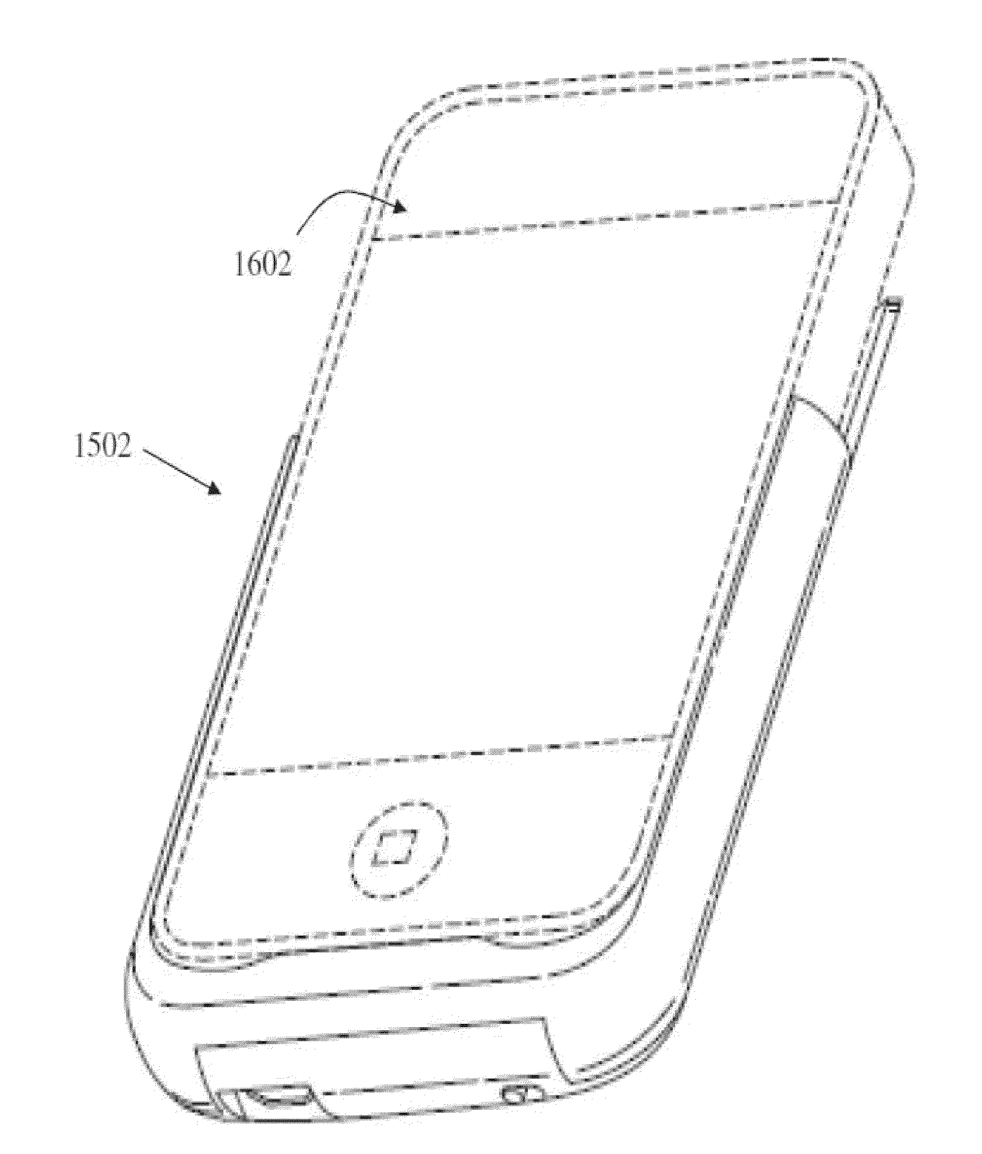
[0125]FIGS. 15-16 and 18-22 illustrate yet another embodiment of the power pack. In this embodiment, the power pack may operate as previously disclosed but does not include a top section. By removing the top section, the battery pack is more compact in size and ergonomic so that it does not significantly increase or change the size, thickness, and / or shape of mobile communication device 1602 secured thereto.

[0126]FIG. 15 illustrates a perspective view of the battery pack 1502.

[0127]FIG. 16 illustrates a perspective view of the battery pack 1502 with a mobile device 1602 inserted therein.

[0128]FIG. 18 illustrates another perspective view of the battery pack 1502.

[0129]FIG. 19 illustrates a front view of the battery pack 1502.

[0130]FIG. 20 illustrates a front view of the battery pack 1502 with the mobile device inserted therein.

[0131]FIG. 21 illustrates a back view of the battery pack 1502 with the mobile device 1602 inserted therein.

[0132]FIG. 22 illustrates a side vie...


PUM


Abstract

A mobile device peripheral that incorporates a repeater antenna inside of a protective case for a mobile device to extend the range of short-range communications while minimizing interference caused by the thickness or materials of the protective case. The repeater antenna can be capable of receiving a wireless signal from an antenna in the mobile device and transmitting the same signal or an amplified version of the same signal. The repeater antenna can be capable of receiving a wireless signal from an external antenna and transmitting the same signal or an amplified version of the same signal to the mobile device. The mobile device peripheral can also include a battery that provides additional power the mobile device. Without a repeater antenna, the materials and / or thickness of the additional battery and / or the case can partially or completely block a short-range, low-frequency, or low-power communication signal such as Near Field Communication (NFC).

Description

CROSS-REFERENCE TO RELATED APPLICATIONS[0001]This application claims the benefit under 35 U.S.C. §119(e) of U.S. Provisional Patent Application No. 61 / 696,139, filed Sep. 1, 2012, and titled “WIRELESS COMMUNICATION REPEATER ANTENNA FOR A MOBILE DEVICE PERIPHERAL,” the entirety of which is hereby incorporated by reference and made a part of this specification for all that it discloses.INCORPORATION BY REFERENCE[0002]The present Application incorporates by reference the following: U.S. patent application Ser. No. 12 / 357,262, entitled “BATTERY PACK, HOLSTER, AND EXTENDIBLE PROCESSING AND INTERFACE PLATFORM FOR MOBILE DEVICES,” and filed Jan. 21, 2009, now U.S. Pat. No. 8,367,235, issued on Feb. 5, 2013; U.S. Provisional Patent Application No. 61 / 021,897, entitled “BATTERY PACK AND HOLSTER FOR MOBILE DEVICES,” and filed Jan. 18, 2008; U.S. Provisional Patent Application 61 / 495,848, entitled “NEAR FIELD COMMUNICATION ACCESSORY FOR A MOBILE DEVICE,” and filed Jun. 10, 2011; U.S. patent ap...

Claims


Application Information

Patent Timeline
Patent Type & Authority Applications(United States)
IPC IPC(8): H05K5/00H02J7/02H04W4/80
CPCH02J7/025H05K5/0086H02J7/0045H04W4/80H04B1/3888H02J7/0048H04M1/72412H04M1/724092H02J50/12H02J50/70
Inventor HUANG, DANIEL
Owner MOPHIE
Why Eureka
Try Eureka