Simplified modal attenuator

Active Publication Date: 2014-04-03
FISHER CONTROLS INT LLC
View PDF3 Cites 7 Cited by
  • Summary
  • Abstract
  • Description
  • Claims
  • Application Information

AI Technical Summary

Benefits of technology

The present invention is about reducing noise from fluid flowing through a pipe. It includes a modal attenuator with a perforated screen and a plurality of rings that disrupt sound waves to reduce fluid noise. The technical effect is to provide an effective and efficient way to reduce noise in fluid flow.

Problems solved by technology

The pressure differences between an inlet and an outlet of the control valve, along with a tortuous flow path through the control valve, produce turbulent fluid flow downstream of the control valve, which causes unwanted and potentially harmful noise.
However, these cage-type noise reducers also reduce fluid flow rates through the cage, which may reduce efficiency of the regulator.
However, such sound absorbing materials have limited effective frequencies and they also reduce fluid flow through the material.
However, the modal suppression device disclosed in MCSD was very heavy and was difficult to assemble.

Method used


Image

  • Simplified modal attenuator
  • Simplified modal attenuator
  • Simplified modal attenuator

Examples


Embodiment Construction

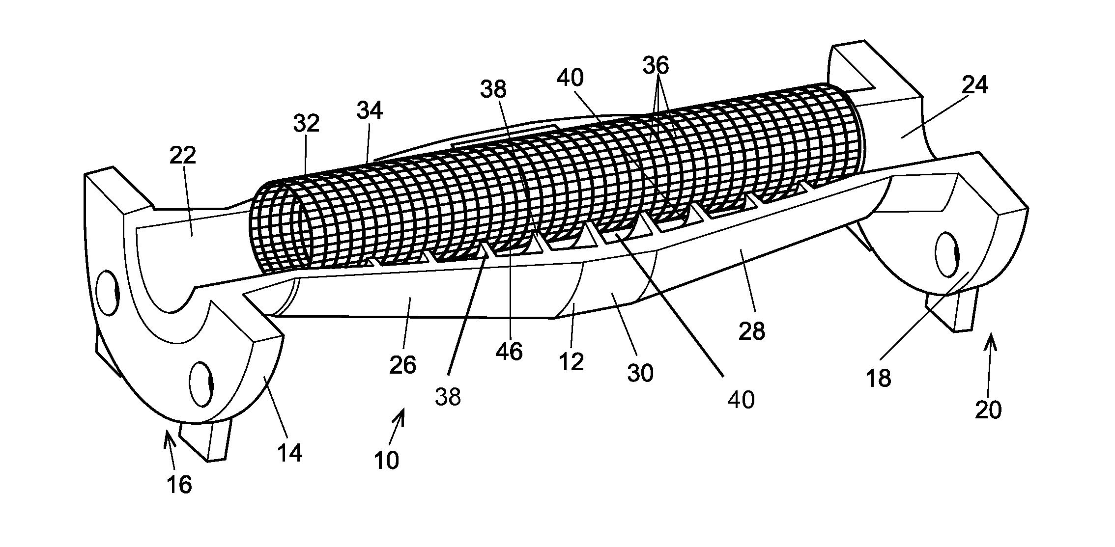
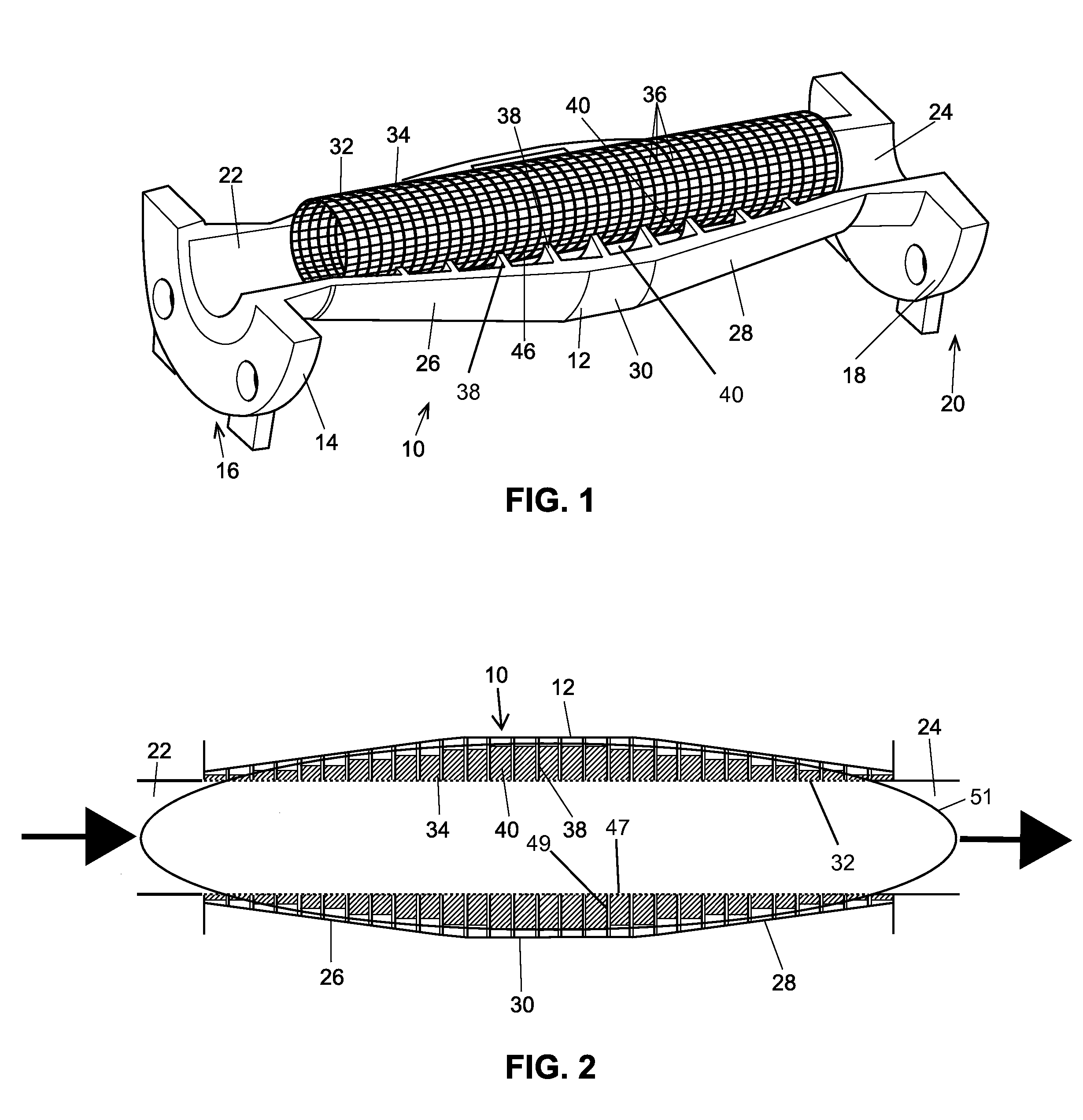
[0022]The modal attenuators described herein advantageously provide noise reduction downstream of regulators or control valves while having very little flow restriction. Thus, the disclosed modal attenuators are highly efficient in reducing noise. The disclosed modal attenuators may be significantly smaller and / or lighter than current noise reduction devices. Thus, the disclosed modal attenuators may be used in regulators or control valves having smaller valve bodies.

[0023]Additionally, a perforated tube in the disclosed modal attenuators may be customized for particular uses by adjusting the transmission index of the perforated tube. Moreover, the disclosed modal attenuators may be combined with more traditional noise suppression devices, such as noise reducing trims, to achieve a more comprehensive noise reduction.

[0024]Generally speaking, the modal attenuators described herein reduce noise in a fluid flowing through a pipe or tube by using sound wave interference to destroy or re...


PUM


Abstract

A modal attenuator may include an attenuator body having a lead-in segment and a lead-out segment joined by a connection segment, a perforated screen disposed within the attenuator body and spaced apart from the attenuator body to form an annular space, and a plurality of rings disposed between the perforated screen and the attenuator body. When fluid flows through the modal attenuator, sound waves pass through the perforated screen and are reflected back by the plurality of rings to disrupt other sound waves, thereby reducing fluid noise in the modal attenuator.

Description

BACKGROUND[0001]1. Field of the Disclosure[0002]The invention generally relates to noise reduction devices for control valves and regulators and more specifically to an in-line modal attenuator for a control valve or regulator.[0003]2. Related Technology[0004]Fluid valves control the flow of fluid from one location to another. When the fluid valve is in a closed position, high pressure fluid on one side is prevented from flowing to a lower pressure location on the other side of the valve. The pressure differences between an inlet and an outlet of the control valve, along with a tortuous flow path through the control valve, produce turbulent fluid flow downstream of the control valve, which causes unwanted and potentially harmful noise.[0005]In an attempt to reduce noise, multi-port cages or trims have been used in some regulators to reduce the pressure drop across the cage and to smooth downstream flow. However, these cage-type noise reducers also reduce fluid flow rates through the...

Claims


Application Information

Patent Timeline
IPC IPC(8): F16L55/033
CPCF16L55/0336F16L55/033G10K11/172F02M35/1266F01N1/026F01N1/02
Inventor FAGERLUND, ALLEN C.GOSSETT, JAMES L.
Owner FISHER CONTROLS INT LLC
Why Eureka
Try Eureka