
Flow-formed differential case assembly
a differential case and assembly technology, applied in mechanical equipment, gearing details, gearing, etc., can solve the problems of difficult welding of differentials formed from cast iron, heavy and volumetrically undesirable, and the assembly of known differentials can be difficult, so as to minimize the required packaging space, facilitate welding, and minimize assembly complexity
- Summary
- Abstract
- Description
- Claims
- Application Information
AI Technical Summary
Benefits of technology
Problems solved by technology
Method used
Image

Examples
Embodiment Construction
[0027]The following description is merely exemplary in nature and is not intended to limit the present disclosure, application, or uses. It should also be understood that throughout the drawings, corresponding reference numerals indicate like or corresponding parts and features.
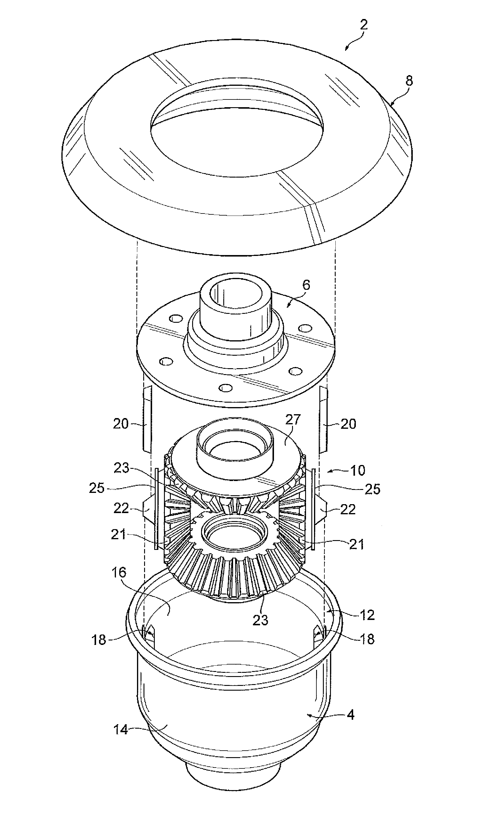
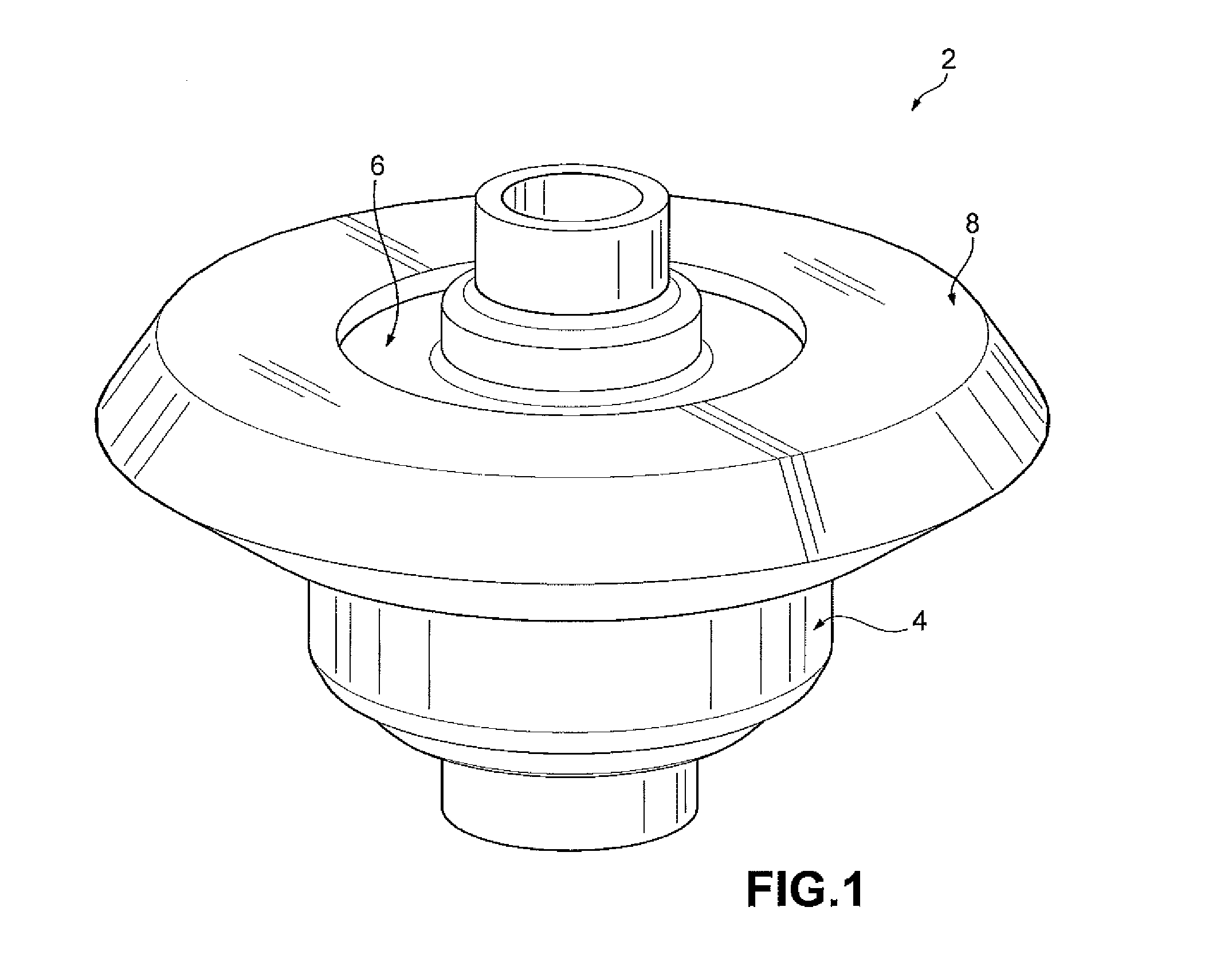
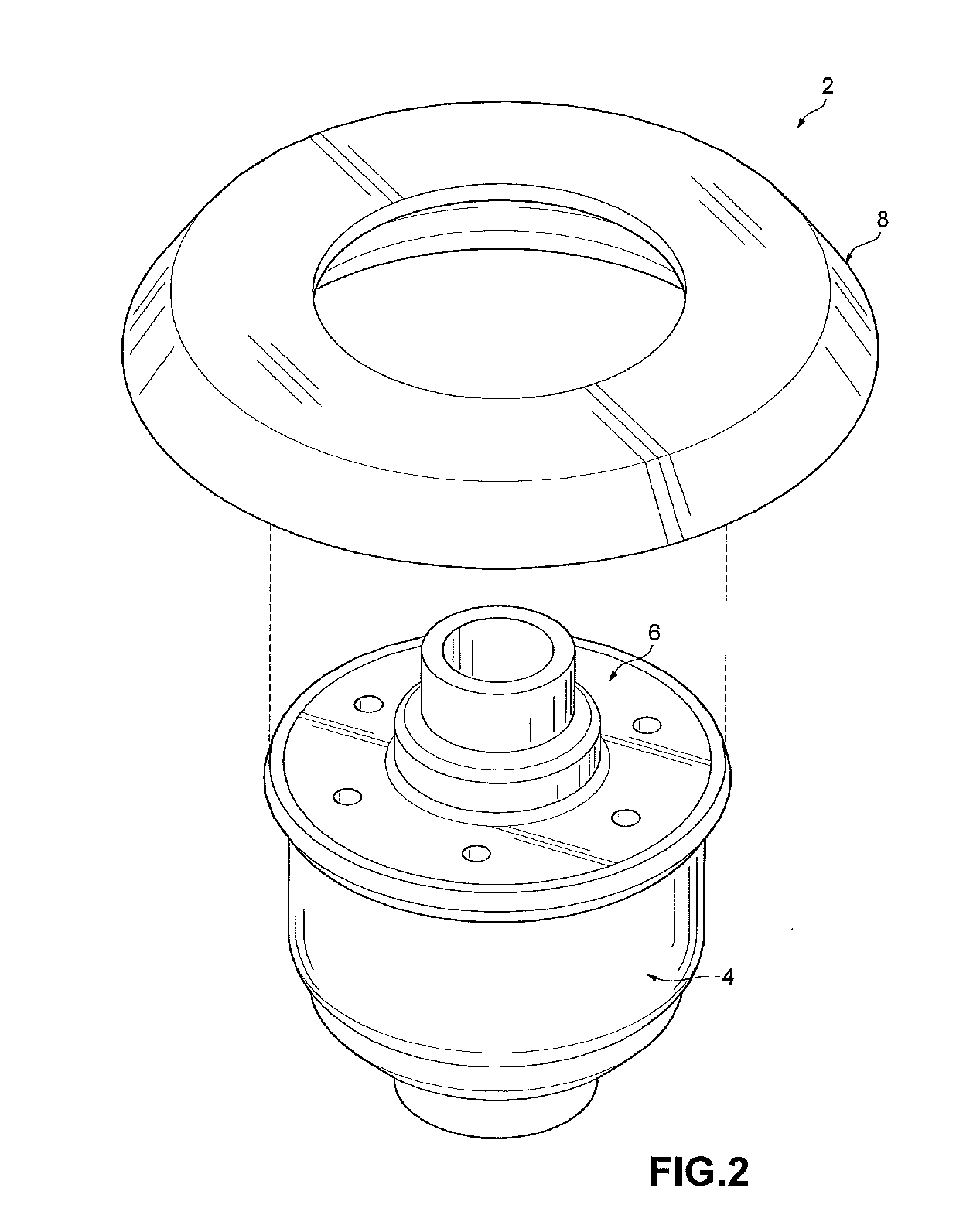
[0028]FIGS. 1-11 depict a differential case assembly 2 according to one embodiment of the present disclosure. With particular reference to FIGS. 1-5, the differential case assembly 2 includes a differential case 4, an end cap 6, a ring gear 8, and a pinless gear assembly 10. The differential case 4, the end cap 6, and the ring gear 8 cooperate to house the pinless gear assembly 10. It should be understood that the pinless gear assembly 10 does not have a cross pin, for example, as disclosed in Assignee's co-pending U.S. patent application Ser. No. 13 / 094,406, the entire disclosure of which is hereby incorporated herein by reference.
[0029]As shown in FIGS. 3-5, the differential case 4 has an open end 12 and a ...
PUM
 Abstract
Description
Claims
Application Information