Flow-formed differential case assembly

a differential case and assembly technology, applied in the direction of gearing details, manufacturing tools, gearing, etc., can solve the problems of difficult welding of differentials formed from cast iron, heavy and volumetrically undesirable, and the assembly of known differentials can be difficult, so as to minimize the required packaging space, facilitate welding, and minimize assembly complexity

Active Publication Date: 2012-12-27
METAL FORMING & COINING
View PDF14 Cites 19 Cited by
  • Summary
  • Abstract
  • Description
  • Claims
  • Application Information

AI Technical Summary

Benefits of technology

[0006]In concordance with the instant disclosure, a differential case assembly that is lighter compared to known cast iron designs, minimizes a required packaging space, minimizes assembly complexity, can be employed with different numbers of gears, facilitates welding, and eliminates a need for multiple nuts / bolts in the assembly process, is surprisingly discovered.

Problems solved by technology

Known differentials have cases that are cast from metals such as iron, and are often heavy and volumetrically undesirable.
Assembly of known differentials can be difficult, oftentimes requiring bolting as well as welding.
Welding of the differentials formed from cast iron, in particular, can undesirably require the use of filler wire to provide an acceptable weld.

Method used


Image

  • Flow-formed differential case assembly
  • Flow-formed differential case assembly
  • Flow-formed differential case assembly

Examples


Embodiment Construction

[0019]The following description is merely exemplary in nature and is not intended to limit the present disclosure, application, or uses. It should also be understood that throughout the drawings, corresponding reference numerals indicate like or corresponding parts and features. In respect of the methods disclosed, the order of the steps presented is exemplary in nature, and thus, is not necessary or critical.

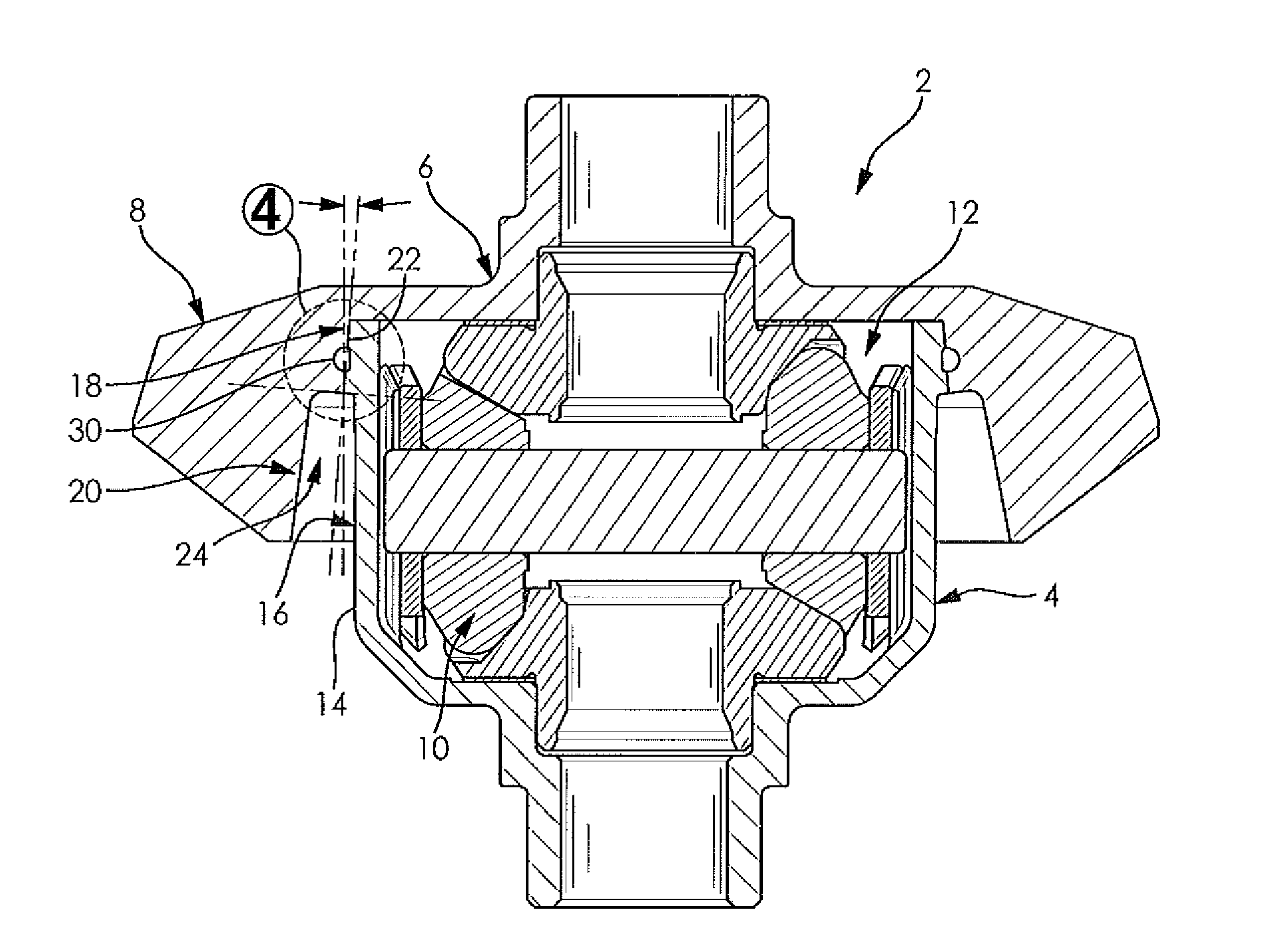
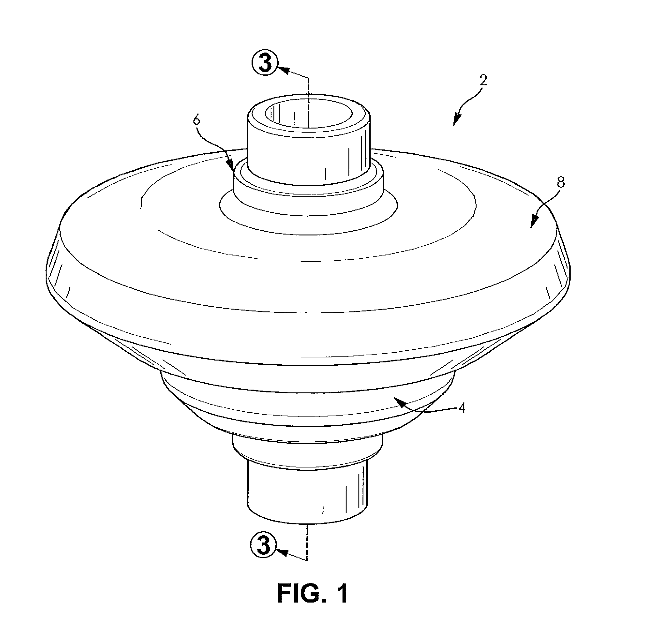
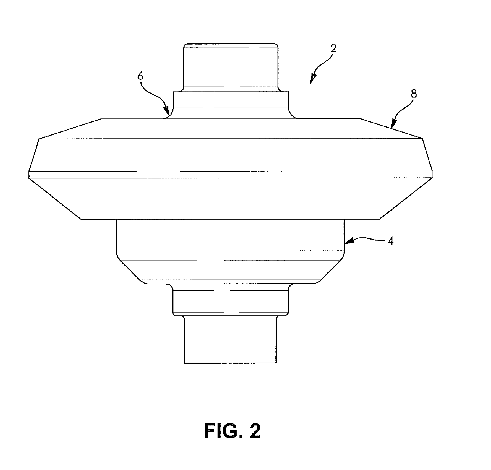
[0020]FIGS. 1-8 depict a differential case assembly 2 according to the present disclosure. The differential case assembly 2 advantageously permits a welding operation from at least one of from “below” the differential case assembly 2 (FIGS. 1-4) and “above” the differential case assembly (FIGS. 5-8), as desired.

[0021]The differential case assembly 2 includes a differential case 4, an end cap 6, a ring gear 8, and a gear assembly 10. The differential case 4, the end cap 6, and the ring gear 8 cooperate to house the gear assembly 10. It should be understood that the gear assembly...


PUM

PropertyMeasurementUnit
angleaaaaaaaaaa
angleaaaaaaaaaa
angleaaaaaaaaaa

Abstract

A differential case assembly includes a differential case and an integral end cap and ring gear assembly. The differential case has an open end and a side wall with an exterior surface. The integral end cap and ring gear assembly is disposed over the open end of the differential case and adjacent the exterior surface. A first interior portion of the integral end cap and ring gear assembly abuts the exterior surface of the differential case to define a weld joint interface. The integral end cap and ring gear assembly is configured to permit a welding operation at the weld joint interface.

Description

CROSS-REFERENCE TO RELATED APPLICATIONS[0001]This application claims the benefit of U.S. Provisional Patent Application No. 61 / 499,929 filed on Jun. 22, 2011. The entire disclosure of the above application is hereby incorporated herein by reference.FIELD OF THE INVENTION[0002]The present disclosure relates to a differential case assembly and, more particularly, to a differential case assembly for use in a motorized vehicle.BACKGROUND OF THE INVENTION[0003]A differential is a device, usually employing gears, that is capable of transmitting torque and permitting rotation of different shafts at different speeds. Known differentials have cases that are cast from metals such as iron, and are often heavy and volumetrically undesirable. Assembly of known differentials can be difficult, oftentimes requiring bolting as well as welding. The use of “feed-in and rotate processes” when cast iron differential cases are manufactured is also known. Welding of the differentials formed from cast iron...

Claims


Application Information

Patent Timeline
Patent Type & Authority Applications(United States)
IPC IPC(8): F16H57/037B23K31/02B23K26/20
CPCF16H48/40Y10T74/2186F16H2048/382F16H2048/085
Inventor CRIPSEY, TIMOTHY J.
Owner METAL FORMING & COINING
Why Eureka
Try Eureka