Force sensing pointing device with click function

a force sensing and pointing device technology, applied in static indicating devices, instruments, contacts, etc., can solve the problems of introducing noise susceptibility, requiring additional circuitry for amplification, and moving the stick creating strain-induced resistance changes, so as to reduce the cost and complexity of an electronic mouse pointing device, and the noise susceptibility is minimal

Active Publication Date: 2005-11-24
INTERLINK ELECTRONICS
View PDF14 Cites 44 Cited by
  • Summary
  • Abstract
  • Description
  • Claims
  • Application Information

AI Technical Summary

Benefits of technology

[0011] The present invention decreases the cost and complexity of an electronic mouse pointing device by constructing the device in a manner permitting assembly into user interfaces with industry standard high v

Problems solved by technology

Moving the stick creates strain induced changes in resistance.
One difficulty with such devices is that the strain induced resistance change creates a small signal, requiring additional circuitry for amplification and introducing noise susceptibility.
In addition, these devices have a flex ci

Method used


Image

  • Force sensing pointing device with click function
  • Force sensing pointing device with click function
  • Force sensing pointing device with click function

Examples


Embodiment Construction

)

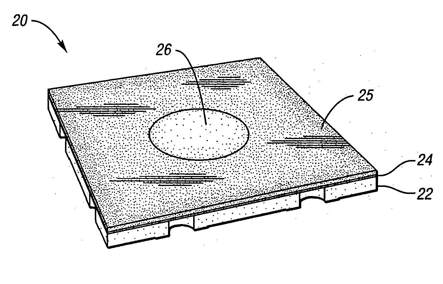
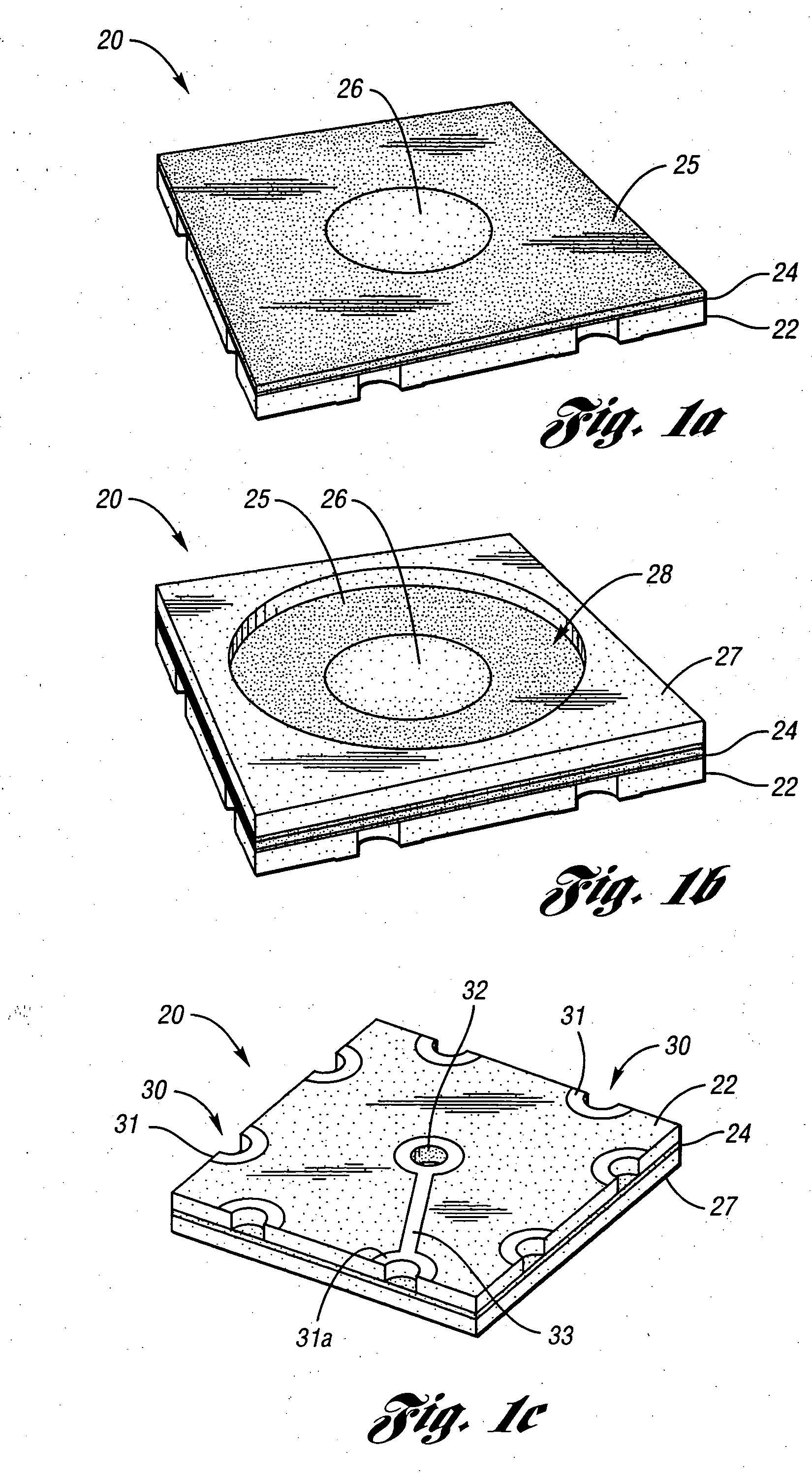
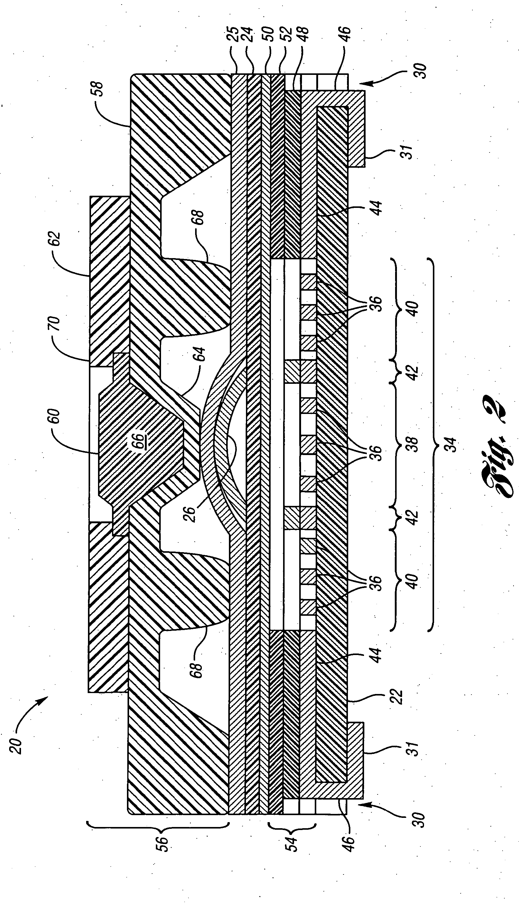
[0039] Referring to FIGS. 1a-1c, perspective views illustrating an input device according to an embodiment of the present invention are shown. An input device, or pointing device shown generally by 20, includes bottom substrate 22, flexible substrate 24 and snap dome membrane 25. Snap dome membrane 25 positions snap dome 26 over flexible substrate 24. In the embodiment shown in FIGS. 1b and 1c, top substrate 27 is placed over snap dome membrane 25. Top substrate 27 defines opening 28 allowing snap dome 24, when properly compressed, to push flexible substrate 24 onto a contact area on bottom substrate 22. In some embodiments of the present invention, top substrate 27 may be eliminated, as is illustrated in FIG. 1a.

[0040] Bottom substrate 22 defines a plurality of vias 30 passing through bottom substrate 22. The bottom side of bottom substrate 22 includes annular conductors 31 surrounding the openings for vias 30. The inside of vias 30 are also conductive. Annular conductors 31 may ...


PUM

PropertyMeasurementUnit
Timeaaaaaaaaaa
Forceaaaaaaaaaa
Flexibilityaaaaaaaaaa

Abstract

An input device for an electronic system includes a force sensor having conductive interdigitated traces on a bottom substrate and a flexible substrate spaced apart from the bottom substrate. The flexible substrate has a resistive layer deposited on a bottom side facing the interdigitated traces. A snap dome is positioned over a portion of the force sensor flexible substrate. A flexible keymat membrane is positioned over the force sensor and the snap dome. The keymat membrane bottom surface faces the force sensor flexible substrate. The keymat membrane bottom surface has a protruding region surrounding the snap dome and spaced above the force sensor flexible substrate. A center keycap on the keymat membrane top surface is positioned over the snap dome. A surrounding keycap on the keymat membrane encloses the center keycap and is positioned over the keymat membrane protruding region.

Description

BACKGROUND OF THE INVENTION [0001] 1. Field of the Invention [0002] The present invention relates to directional input devices particularly for use in portable electronic devices. [0003] 2. Background Art [0004] Highly portable electronic devices, such as personal digital assistants, portable telephones, remote controls, and the like, provide increasing functionality to their users. This functionality often accompanies an increased need for information from the user. To fulfill this need, portable electronic devices incorporate mouse pointing sensors that provide directional input using a single finger, often from the same hand that holds the electronic device. In addition, many such mouse pointing sensors provide a magnitude signal in relation to force supplied by the user. This force may be applied through a joystick or a mouse button. Many applications also require or are assisted by a selection input. Signals generated by such mouse pointing sensors are conditioned and processed...

Claims


Application Information

Patent Timeline
IPC IPC(8): G06F3/0338G06F3/041G09G5/00H05K3/34
CPCH05K3/3442G06F3/0414G06F3/0338H01H25/041G06F3/0202H01H2025/048H01H2221/012H01H2201/036H01H2203/02H01H2213/00H01H2229/028H01H2215/006H01H2215/012H01H13/785
Inventor BAKER, JEFFREY ROSSTICKLE, JAMES DEXTERSANCHEZ, CARLOS SOLISALHART, SCOTT DAVID
Owner INTERLINK ELECTRONICS
Why Eureka
Try Eureka