Flow-formed differential case assembly

a differential case and assembly technology, applied in mechanical equipment, gearing details, gearing, etc., can solve the problems of difficult welding of differentials formed from cast iron, heavy and volumetrically undesirable, and the assembly of known differentials can be difficult, so as to minimize the required packaging space, facilitate welding, and minimize assembly complexity

Active Publication Date: 2014-01-14
METAL FORMING & COINING
View PDF37 Cites 4 Cited by
  • Summary
  • Abstract
  • Description
  • Claims
  • Application Information

AI Technical Summary

Benefits of technology

[0005]In concordance with the instant disclosure, a differential case assembly that is lighter compared to known cast iron designs, minimizes a required packaging space, minimizes assembly complexity, can be employed with different numbers of gears, facilitates welding, and eliminates a need for multiple nuts / bolts in the assembly process, is surprisingly discovered.

Problems solved by technology

Known differentials have cases that are cast from metals such as iron, and are often heavy and volumetrically undesirable.
Assembly of known differentials can be difficult, oftentimes requiring bolting as well as welding.
Welding of the differentials formed from cast iron, in particular, can undesirably require the use of filler wire to provide an acceptable weld.

Method used


Image

  • Flow-formed differential case assembly
  • Flow-formed differential case assembly
  • Flow-formed differential case assembly

Examples


Embodiment Construction

[0027]The following description is merely exemplary in nature and is not intended to limit the present disclosure, application, or uses. It should also be understood that throughout the drawings, corresponding reference numerals indicate like or corresponding parts and features.

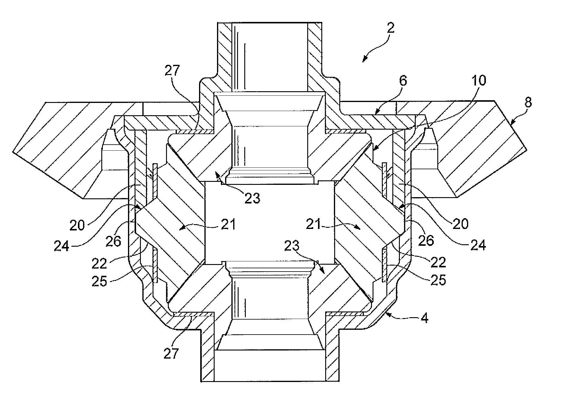
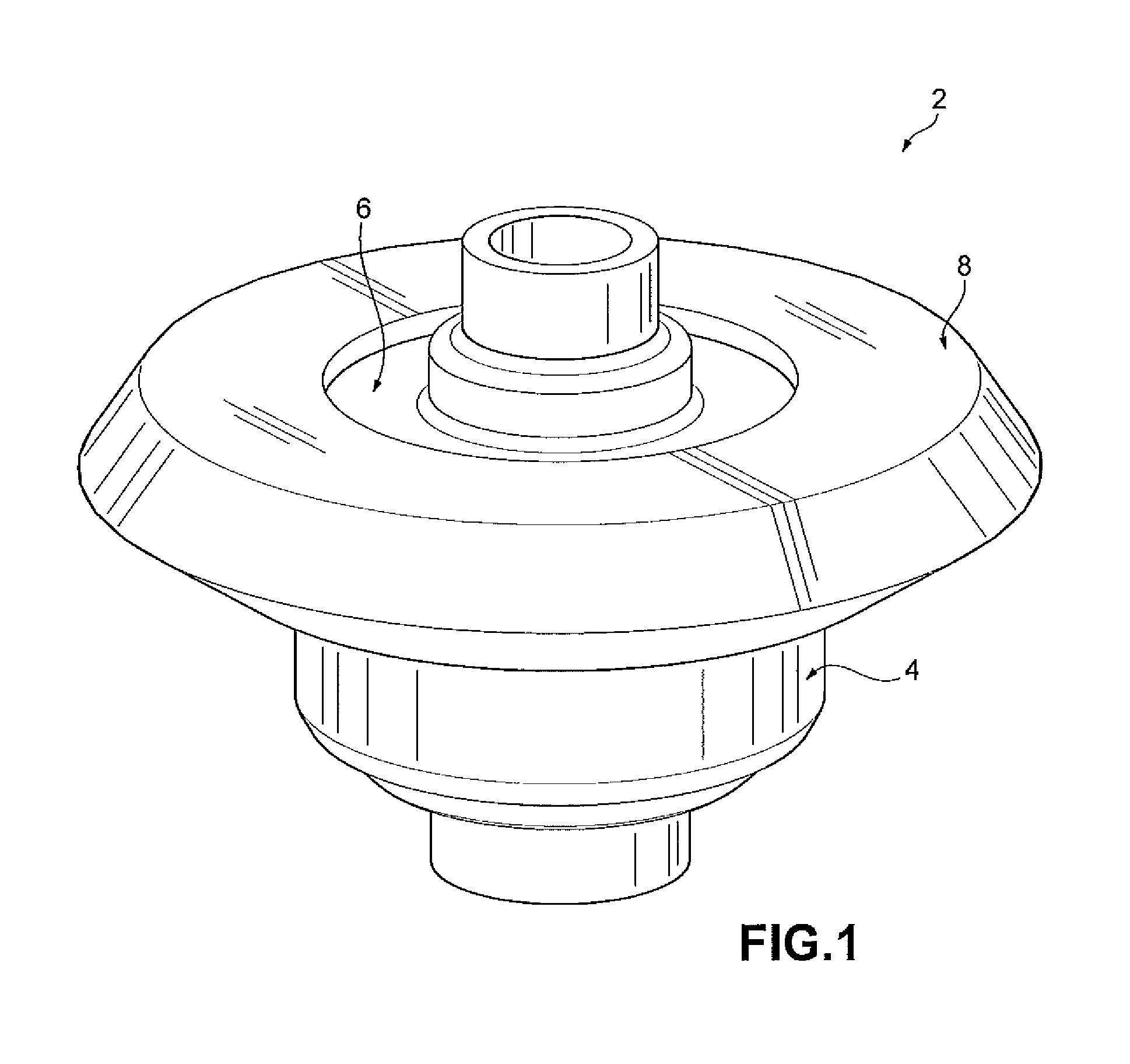
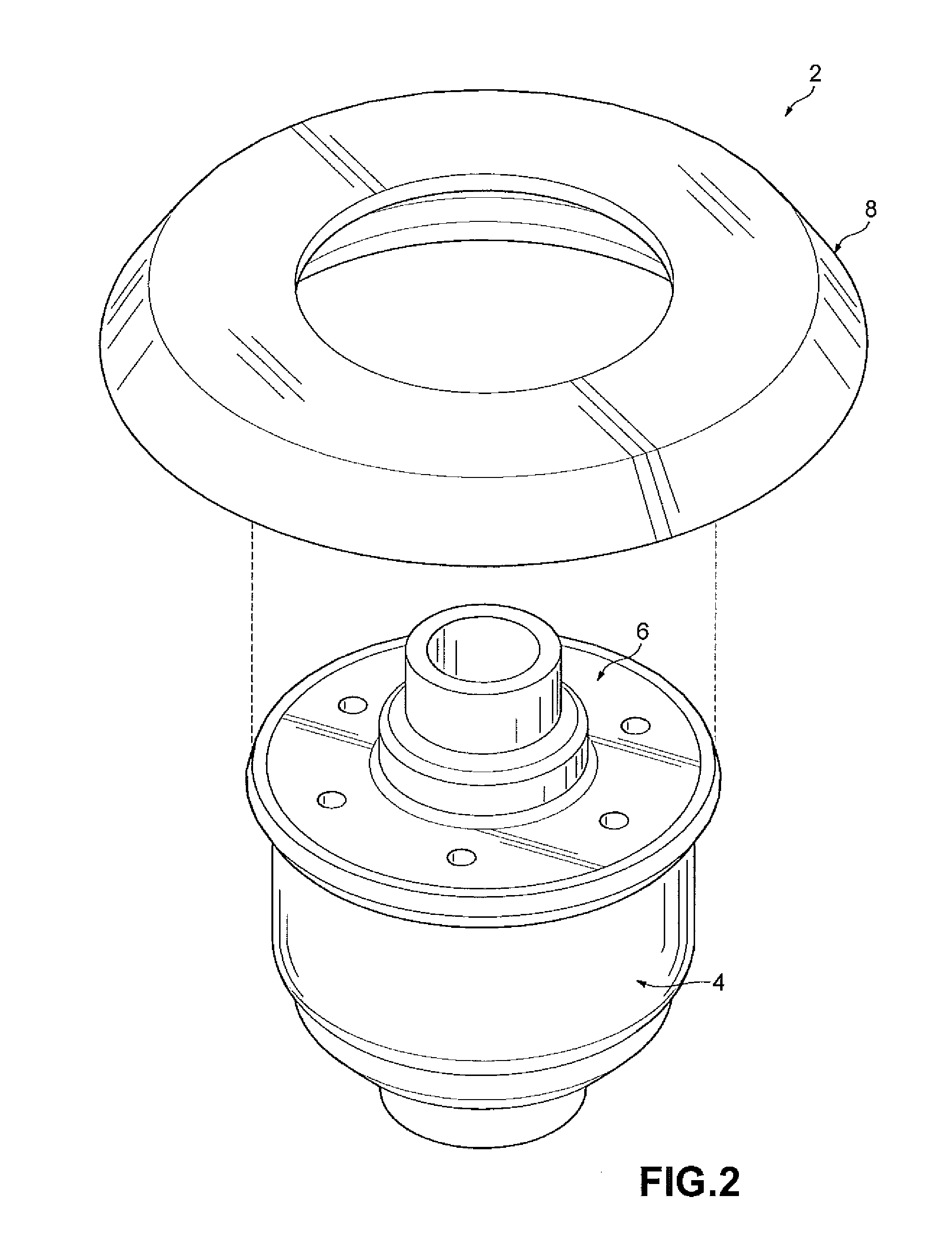
[0028]FIGS. 1-11 depict a differential case assembly 2 according to one embodiment of the present disclosure. With particular reference to FIGS. 1-5, the differential case assembly 2 includes a differential case 4, an end cap 6, a ring gear 8, and a pinless gear assembly 10. The differential case 4, the end cap 6, and the ring gear 8 cooperate to house the pinless gear assembly 10. It should be understood that the pinless gear assembly 10 does not have a cross pin, for example, as disclosed in Assignee's co-pending U.S. patent application Ser. No. 13 / 094,406, the entire disclosure of which is hereby incorporated herein by reference.

[0029]As shown in FIGS. 3-5, the differential case 4 has an open end 12 and a ...


PUM


Abstract

A differential case assembly includes a differential case and a pinless gear assembly. The differential case has an open end and a side wall with an interior surface. The pinless gear assembly includes a retainer insert and a side gear with a shaft extending outwardly therefrom. The retainer insert is disposed adjacent the interior surface of the side wall, The retainer insert defines at least a portion of an aperture that receives an end of the shaft to align the gear assembly within the differential case.

Description

CROSS-REFERENCE TO RELATED APPLICATIONS[0001]This application claims the benefit of U.S. Provisional Patent Application No. 61 / 360,726 filed on Jul. 1, 2010. The entire disclosure of the above application is hereby incorporated herein by reference.FIELD OF THE INVENTION[0002]The present disclosure relates to a differential case assembly and, particularly, a differential case assembly for use in a motorized vehicle.BACKGROUND OF THE INVENTION[0003]A differential is a device, usually employing gears, that is capable of transmitting torque and permitting rotation of different shafts at different speeds. Known differentials have cases that are cast from metals such as iron, and are often heavy and volumetrically undesirable. Assembly of known differentials can be difficult, oftentimes requiring bolting as well as welding. The use of “feed-in and rotate processes” when cast iron differential cases are manufactured is also known. Welding of the differentials formed from cast iron, in part...

Claims


Application Information

Patent Timeline
Patent Type & Authority Patents(United States)
IPC IPC(8): F16H37/06F16H48/06
CPCF16H2048/382F16H48/40F16H48/08F16H48/38F16H2048/085F16H2048/087Y10T74/2186Y10T74/2188
Inventor CRIPSEY, TIMOTHY J.HERSTON, ROBERT J.
Owner METAL FORMING & COINING
Why Eureka
Try Eureka