Dynamic axial nail for intramedullary treatment of long bone fractures

a technology of axial nail and long bone fracture, which is applied in the field of intramedullary nail, can solve the problems of significant pain for patients, loss of bone quality and quantity, and inability to completely heal bone, so as to encourage and accelerate bone healing

a technology of axial nail and long bone fracture, which is applied in the field of intramedullary nail, can solve the problems of significant pain for patients, loss of bone quality and quantity, and inability to completely heal bone, so as to encourage and accelerate bone healing

US20140135769A1Active Publication Date: 2014-05-15ZIRAN NAVID

Image

  • Dynamic axial nail for intramedullary treatment of long bone fractures
  • Dynamic axial nail for intramedullary treatment of long bone fractures
  • Dynamic axial nail for intramedullary treatment of long bone fractures

Examples


Embodiment Construction

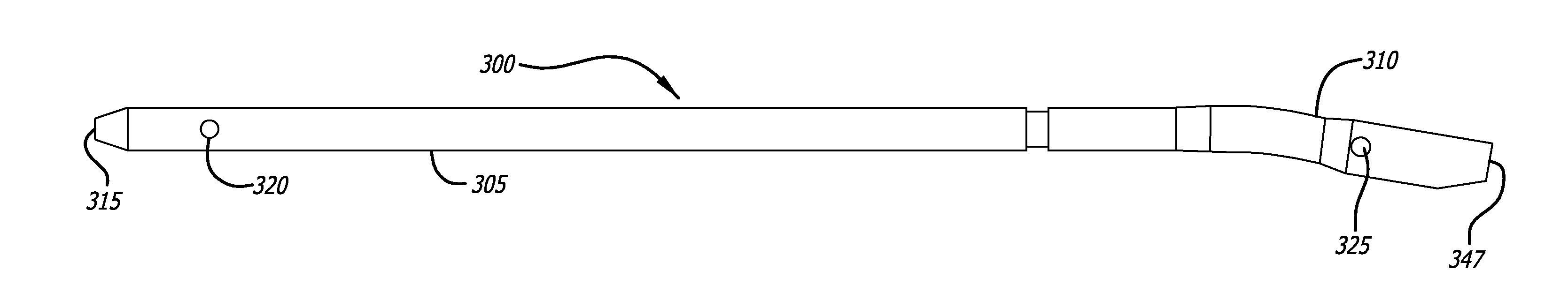
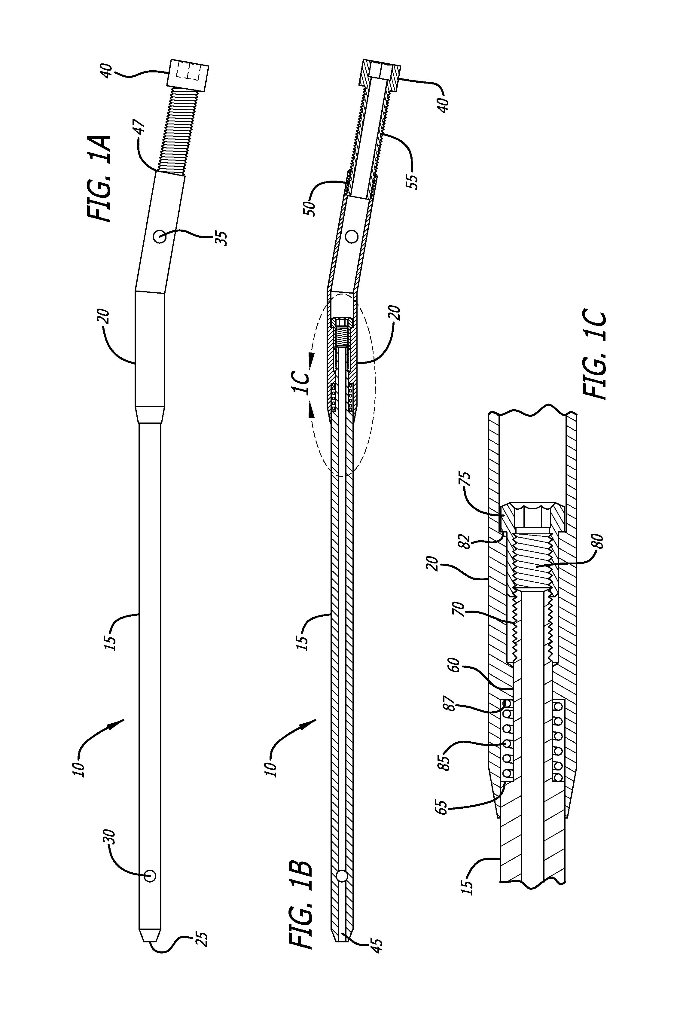
[0044]Referring now to the drawings in detail, in which like reference numerals indicate like or corresponding elements among the several figures, there is shown in FIG. 1A an exemplary embodiment of an intramedullary nail 10 in accordance with the present invention. Nail 10 includes a distal portion 15 and a proximal portion 20. As will be discussed in more detail below, the distal and proximal portions are engaged in a manner that allows each portion to move a limited amount independently of the other portion.

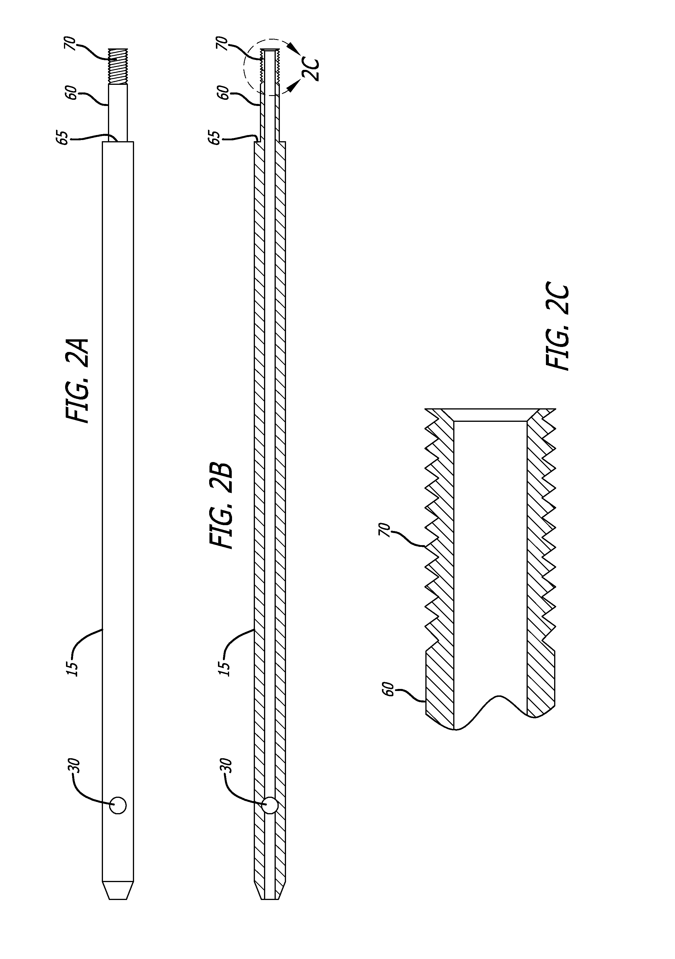
[0045]Distal portion 15 includes an end port 25 disposed at a distal end of the distal portion 15. A fixation hole 30 is also disposed near the distal end of distal portion 15. Fixation hole 30 is sized to receive a screw or other fastener that may be used to attached distal portion 15 to bone surrounding distal portion 15 when the nail 10 is positioned within the medullary space of a bone so as to fixate and stabilize a fracture in the bone.

[0046]Referring now to FIGS. 1A an...


PUM


Abstract

An intramedullary nail for fixation and stabilization of a fractured bone that also allows for a controlled amount of longitudinal motion at the fracture site to encourage bone remodeling and healing is described. The intramedullary nail has a proximal portion and a distal portion that are coupled together in a manner by a biasing assembly that provides for a controlled movement of the proximal and distal portions relative to each other so that when a patient puts pressure on the bone, such as when walking, the fracture site compresses and the bone ends move together, and when the pressure is released from the bone, the bone ends are biased apart by a controlled amount.

Description

CROSS-REFERENCES TO RELATED APPLICATIONS[0001]This application claims priority from U.S. Application No. 61 / 725,429, filed Nov. 12, 2012 incorporated by reference in its entirety.BACKGROUND[0002]This invention relates to an intramedullary nail for use in stabilizing and enhancing the healing of broken bones, and more particularly to an intramedullary nail that includes motion along its longitudinal axis so as to elicit an improved healing response in the bone in which the nail is placed.[0003]It is well known in the art that functional loading of skeletal bone results in changes to bone quality and quantity. Conversely, lack of mechanical loading has been found to lead to a loss of bone quality and quantity.[0004]When a bone fractures, one of two physiological processes are stimulated that provide for healing of the fracture. The first process is denoted enchondral ossification and occurs when there is strain at the fracture site. This process forms bone through a cartilage intermed...

Claims


Application Information

Patent Timeline
15 May 2014
Publication
US20140135769A1
IPC
A61B17/72
CPC
A61B17/72; A61B17/7216; A61B2017/00991; A61B2017/681; A61B17/7225
Inventors
ZIRAN, NAVID